Transcription of UPM DT 1 & 10AV - Users manual - metlog-biomed.eu
1 508 August St. Easton, MD 21601 Voice: (410) 820-5111 Fax: (410) 822-9633 ultrasound power METER Model UPM-DT-1 & 10AV OPERATOR S manual Ohmic Instruments Company 2006 TABLE OF CONTENTS Unpacking the UPM-DT-1&10AV .. 3 Replacement Parts .. 3 Selecting a Location for Operation .. 4 Panel Controls and Display Indicator .. 4 Operating Procedure .. 4,5 Transporting the UPM-DT-1&10AV .. 5 General Operating Notes .. 5 Set Up .. 6 Calibration .. 6 Serial Computer/Printer Interface .. 6 Programming Print Control .. 7 RS-232 .. 7,8 Output Formats .. 8 Shipping Instructions for the UPM-DT-1&10AV .. 9 Specifications .. 9 Maintenance .. 10 Water, Tank Size, Transducer Placement & Temperature Considerations .. 10 ultrasound Radiation Levels .. 10 Theory of Measuring ultrasound power With the Radiation Force Method .. 11 Sample Inspection Record (2 pages).
2 13,14 All rights reserved. This manual may not be reproduced in complete form without written permission of Ohmic Instruments Company. Test forms may be copied as required by the original purchaser of the instrument. Information contained in this manual is believed to be accurate and reliable; however, no responsibility is assumed by Ohmic Instruments Company for its use. Ohmic reserves the right to supply its instruments with design changes and/or component substitutions that may not be documented in this manual . INTRODUCTION Measurement of power output levels of diagnostic and therapeutic ultrasound equipment has become increasingly im-portant to determine exact patient exposure levels in case a potential risk exists to the patient. Since the Radiation Control for Health & Safety Act of 1968 and the 1976 Medical Device Amendments to the FDA Act became effective, all manufacturers of diagnostic Doppler ultrasound equipment are required to submit information regarding their maxi-mum peak and average exposure level, beam patterns, and other pertinent information.
3 Hospitals are responsible for regularly scheduled testing (every six months) of output power and safety to maintain their accreditation. The ultrasound power Meter, Model UPM-DT-1&10AV, are designed to measure the ultrasound power output of diag-nostic or therapeutic transducers up to 30 watts. The principle of measurement is the radiant force method. The UPM-DT-1&10AV use a positioning clamp to hold the transducer in de-gassed water above a conical target. The ultra-sonic energy passes through the water to reflect off the target and is then absorbed by the rubber lining. The radiant power is directly proportional to the total downward force (weight) on the target. This weight is then transferred through the target support assembly to the electro-mechanical load cell inside the scale. The cell is in a computer-controlled feedback loop and produces a digital readout in watts of power (custom units) or grams of force.
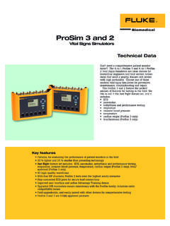
4 The choice of units (grams or watts) is selected by front panel pushbuttons. The UPM-DT-1&10AV are supplied with a plug-in 120 VAC to 12 VDC 400 mA adapter (using another adapter not rated the same may damage unit). The UPM-DT-1AV has a display resolution of 2 milliwatts. The UPM-DT-10AV has a display resolution of 20 milliwatts. UNPACKING THE UPM-DT-1&10AV The power meter comes complete with all accessories in a sturdy carrying case. To make ultrasonic measurements, the water tank requires only one pint of de-gassed distilled water. If de-gassed water is not available, use distilled wa-ter, NOT tap water. The following replacement parts can be ordered if necessary from Ohmic : Front view of the UPM-DT-1&10AV. Shown is the electronic balance, base assembly, and test tank. REPLACEMENT PARTS Test Tank with Rubber Positioning Clamp Assembly Cone Assembly Calibration Weight Standards (ORDER BOTH NUMBERS #49025-12 and # 49045-12.)
5 120 VAC to 12 VDC 500 mA power adapter # 12102320 Instruction manual [specify ; available in PDF format] Carrying Case 3 SELECTING A LOCATION FOR OPERATION The UPM-DT-1&10AV should always be used in an environment free from excessive air currents, corrosives, vibration and temperature or humidity extremes. These factors will affect the displayed readings. DO NOT operate the UPM-DT-1&10AV: Next to open windows or doors causing drafts or rapid temperature changes Near air conditioning or heat ducts Near vibrating, rotating or reciprocating equipment Near magnetic fields or equipment that generate magnetic fields On an non level work surface Allow sufficient space around the instrument for ease of operation and keep away from radiant heat sources. Never set any material on the UPM-DT-1&10AV or place your hands or fingers on it while taking readings.
6 PANEL CONTROLS & DISPLAY INDICATOR Off - Yes button ; Press to turn unit on or zero, press and hold until OFF is displayed then release to turn off. Unit - No button ; Press to print, press and hold then release when unit desired is displayed. Mode - Back button Menu-Cal - Exit button ; Press to tare 5. 7 - segment display ; Shows readings. A g after the reading indicates grams. 6. Stability Indicator 7. 14 - segment display ; Shows units, Custom is watts. 8. Symbols for weighing units are: Grams Mode Custom Mode (Watts) UPM-DT-1AV UPM-DT-10AV OPERATING PROCEDURE 1. Remove the top of the carrying case by unlatching the clamps located on two ends. The UPM-DT-1&10AV are mounted on the base of the carrying case.
7 2. Place the UPM-DT-1&10AV on a stable and level surface. Avoid air currents and mechanical vibrations. Level unit as much as possible. 3. Loosen the positioning clamp and position out of the way, remove cone target from the clips on the table tube and test tank where it is normally stored. Tank is positioned on the rubber circle. 4. Fill the test tank to inch below the top of the rubber liner with recently de-gassed water at room temperature. (To obtain de-gassed water, boil distilled water for 20 minutes, fill a jar completely, cover, and allow to cool). 1 2 3 4 5 6 7 4 5. Plug the AC Adapter into a 120 VAC, 60 Hz power outlet and plug it into the power jack at the rear of the unit. De-press the ON/Zero/Off button. 6. Lower the cone target into the concentric target support sleeve located to the back/left of the test tank (small tube inside of larger tube ), while simultaneously placing the cone target into the tank.
8 If the cone can swing in an arc, it is not down far enough. Tip the rod back and forth slightly to fully engage the rod. Press the ON/Zero/Off button. 7. By means of the positioning clamp, attach the transducer head and place its radiating face 1/8 to 1/4 inch below the water level, parallel to the water surface, and directly above the center of the cone. Check transducer surface for uniform wetting (no air pocket or bubbles should be on its surface). 8. Allow 5 minutes for the scale to stabilize. With no ultrasonic power applied to the transducer, press the ON/Zero/Off button to zero the unit. 9. Check response by placing the 1 gram weight on the arm of the cone target ( the flat part that is out of the water). The UPM-DT-1AV(10AV) should read ( ) grams ( ). Change the units to the watts mode by pressing and holding the Print Unit button until the unit desired is displayed then release.
9 The UPM-DT-1AV (10AV) should read ( ) watts ( ) watts. 1 gram is equal to watts. 10. Remove the 1 gram weight. Press the ON/Zero/Off button to zero the unit. power to the Transducer Under Test (TUT). Re-zero before each measurement and take your power reading when the display has stabilized. It is a good practice to take three readings and average them. If measurement con-ditions are not stable, use the grams mode and multiply the readings by to obtain watts the maximum peak power with the maximum duty cycle and pulsed output settings with the equation: PAVE = Pp Rtpa PAVE = calculated average power Pp = Peak Pulsed power Setting on unit under test Rtpa = Ratio of Temporal Peak to Average power (from each manufacturer) 13.
10 To calculate the watts/cm2 output, take the total watts reading from the unit and divide by the area. The area is d2 4 (d is the diameter of the transducer) if the transducer is smaller than the cone. Otherwise, use ( cm) the cone s diameter as the area. 14. When finished, unplug the UPM-DT-1&10AV, empty the tank, and place the dry target cone in the tank for protec-tion. TRANSPORTING THE UPM-DT1&10AV Lift off the target cone assembly from the sleeve, empty water into a storage container, dry the tank and cone, place cone in the tank and clamp the target rod into the storage clips on the side of the target sleeve. Place the power supply in the tank. Rotate the transducer clamp arm over the top of the tank and stretch the large rubber band between the two hooks of the hold-down clip, over the clamp arm and tank. Place the carrying case cover over the base and secure the latches (for shipping instructions see Page 9 ).