Transcription of UPS12-270 VALVE REGULATED LEAD ACID BATTERY
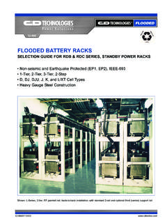
1 41-7108 UPSUPS12-270 VALVE REGULATEDLEAD acid BATTERYFOR UPS STANDBY POWER APPLICATIONS 12V 75 AH @ 20 HR RATE,12V 282 WATTS/CELL @ 15 MIN. RATEO perating Time to End Point Voltage (in Minutes)5 1015 2030 40 45 506090 52436128223317614112911910476 SPECIFICATIONS12 Volts 282 Watts Per Cell For 15 Minutes to Volts per CellConstant Power Discharge Ratings Watts Per Cell @ 77 F (25 C) 10 Year design life @ 25 C (77 F) Absorbent Glass Mat (AGM) technologyfor efficient gas recombination of up to99% and freedom from electrolytemaintenance.
2 Patented flame-arresting one-way pressure-relief vent providing vacuumand controlled backpressure for long liferecombinant operation. Designed to comply with ANSI andEurobat BATTERY standards. Specifically designed for optimum performance in UPS applications. Proprietary computer modeled radialgrid matrix using multiple conductors forproviding the lowest internal resistanceand highest current carrying efficiency. Proprietary Fixed Orifice Pasting technology applying active material onboth sides of the grid for consistent cell-to-cell performance, highest paste packingefficiency and uniform grid protection.
3 Lowest calcium levels among batterymanufactures minimizing grid growthand extended BATTERY life. UL-recognized component. Thermally welded case-to-cover bond to eliminate leakage. Can be mounted in any , side, or end mounting recommended. Not restricted for air transport Complies with IATA/ICAO SpecialProvision A67. Not restricted for surface transport Classified as non-hazardous material as related to DOT-CFR Title 49 parts 171-189. Flame retardant polypropylene case and cover compliant with UL 1778(optional). PointVolts/CellLEADRETURNRECYCLEAny data, descriptions or specifications presented herein are subject to revision by C&D Technologies, Inc.
4 Without notice. While such information is believed to be accurate as indicated herein, C&D Technologies, Inc. makes no warranty and hereby disclaims all war-ranties, express or implied, with regard to the accuracy or completeness of such information. Further, because the product(s) featuredherein may be used under conditions beyond its control, C&D Technologies, Inc. hereby disclaims all warranties, either express orimplied, concerning the fitness or suitability of such product(s) for any particular use or in any specific application or arising fromany course of dealing or usage of trade.
5 The user is solely responsible for determining the suitability of the product(s) featured here-in for user s intended purpose and in user s specific 2004 C&D TECHNOLOGIES, INC. Printed in 41-7108 UPS 5M/305/DL41-7108 UPS900 East Keefe AvenueMilwaukee, WI 53212 (414) 967-6500 Fax (414) 961-6506 (800) to be mounted with in. ( cm) spacing minimum and free air ventilation. Specifications subject to change without watts per cell at the 15 minute rate to volts per cell at 77 F (25 C).Capacity75 Ah @ 20 hr. rate to volts per cell @ 77 F (25 C).
6 66 Ah @ 10 hr. rate to volts per cell @ 68 F (20 C).Operating Temperature RangeDischarge;-40 F (-40 C) to +160 F (71 C), Charge; -10 F (-23 C) to +140 F (60 C).(with temperature compensation)Nominal Operating Temperature Range+74 F (23 C) to +80 F (27 C).Float Charging to VDC/unit Average at 77 F (25 C).Recommended Maximum Charging Current LimitC/5 amperes (15 amperes @ 100% depth of discharge) @ 20 hour rateEqualization and Cycle Service Charging to VDC/unit average at 77 F (25 C).Maximum AC Ripple (Charger) RMS or P-P of float charge voltage recommended for best results.
7 Maximum voltage allowed = RMS (4% P-P). Maximum current allowed = amperes rms (C/20).Self DischargeDynasty UPS batteries may be stored for up to 6 months at 77 F (25 C) and then a freshening chargeis required. For higher temperatures the time interval will be unit connectors, racks and cabinet systems are L terminal with clearance hole to accept (6mm) Hardware Initial Torque40 ( N-m).Terminal Hardware Annual Retorque32 ( N-m).SPECIFICATIONSC ellsPer Unit6 VoltagePer kgElectrolyteAbsorbed H2SO4SG = Current800 AmpsShort CircuitCurrent3600 Amps@ Hz ( ) OhmsOperating Time to End Point Voltage (in hours)Constant Current Discharge Ratings Amperes @ 77 F (25 C).
8 PointVolts/CellOperating Time to End Point Voltage (in minutes)Constant Power Discharge Ratings Watts Per Cell @ 77 F (25 C)5 PointVolts/Cell