Transcription of USB Superspeed Equalizer Design Guidelines (2011 …
1 USB Superspeed Equalizer Design Guidelines USB Super Speed Equalizer Design Guidelines Contents 1. Introduction .. 1 Purpose .. 1 Overview .. 1 Organization .. 2 References .. 2 Additional notes .. 2 2. Channel Environment .. 3 Full Link Models .. 3 Compliance 4 3. Equalization in Superspeed USB .. 7 Transmitter Equalization .. 7 Receiver Equalization .. 7 Equalizer Training Sequence .. 8 4. Results .. 10 Introduction .. 10 Full Link 10 Compliance Simulations .. 13 Supplemental Compliance Environment .. 14 5. Summary and Recommendations .. 18 USB Superspeed Equalizer Design Guidelines 1. Introduction Purpose This document describes the trade-offs involved in defining and designing the equalization circuits for USB Superspeed transceivers.
2 The descriptions include the range of interconnect channels and their electrical characteristics, key features of the USB specification for enabling Equalizer optimization, parameters describing Equalizer behavior and recommended operating ranges for each, and considerations for implementation of the Equalizer training. The physical layer section (chapter 6) of the USB specification [1] defines informative and normative specifications for Superspeed transceivers. This document is intended to supplement the specification and to provide guidance to transceiver designers. Overview Historically, Universal Serial Bus usage has spanned a wide range of interconnection environments.
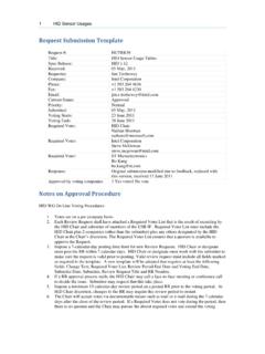
3 Examples of the range are shown in Figure 1. The short channel in the figure represents a device that plugs directly into the host connector (such as a memory stick) with a host controller that is as close as possible to the host port connector ( A . connector). The printed circuit board routing for such devices tends to be very short as well, perhaps as small as 10mm. Due to the short transmission lines, this configuration will have a relatively low differential insertion loss, perhaps as little as -4dB at the fundamental frequency for the signal ( ). At the other extreme, the long channel connects the USB device to the controller through a 3 meter long cable.
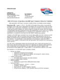
4 In addition, the traces on the printed circuit board are routed at the maximum length (approximately 10 ) and may contain multiple layer-layer transitions using through-hole vias. In addition, the routed length on the device may be up to 50mm (2 ) in length. In this case the differential insertion loss for the channel is expected to be in the range of -17dB to -18dB at Figure 1. USB interconnect channel application range. At multiple gigabit per second (Gb/s) data rates, frequency dependent losses from the interconnect channel cause it to act like a low pass filter. This filtering effect has a smearing effect on the signals, which results in a reduced eye opening, as illustrated in Figure 2(b).
5 Superspeed USB uses equalizers at the transmitter and receiver to counter the effects of the channel, as seen in Figure 2(c). [2] The interactions between the channel and Equalizer Design are a key focus of the remainder of this document. 1. USB Superspeed Equalizer Design Guidelines 500 500 500. 400 400 400. 300 300 300. 200 200 200. 100 100 100. voltage (mV). voltage (mV). voltage (mV). 0 0 0. 100 100 100. 200 200 200. 300 300 300. 400 400 400. 500 500 500. 0 10 20 30 40 50 60 70 80 90 100 110 120 130 140 150 160 170 180 190 200 0 10 20 30 40 50 60 70 80 90 100 110 120 130 140 150 160 170 180 190 200 0 5 10 15 20 25 30 35 40 45 50 55 60 65 70 75 80 85 90 95 100.
6 Time (ps) time (ps) time (ps). (a) transmitter output (b) receiver input (c) Equalizer receiver input Figure 2. Channel loss impact on data eye. Organization The document is organized as follows: Chapter two provides additional detail on the channel environment, including descriptions of the key mechanisms that impact the data eye. Models for the compliance channel are introduced, including the reference Equalizer transfer function. Chapter three describes the models for transmit and receive equalizers, introduces the key parameters for describing their behavior, and describes the reference Equalizer for use in transmitter compliance testing using the existing compliance channel.
7 In addition, it describes the approach to optimizing the behavior of the Equalizer Design that is provided for by the USB specification. Chapter four presents simulation results that demonstrate the impacts of the varying interconnect channels on the data eye and on the equalization requirements for the system. The chapter also introduces a supplemental compliance channel and reference Equalizer for use in ensuring sure that a transceiver Design operates robustly in a low loss environment. Chapter four demonstrates the requirements for the Equalizer behavior. Specific focus is placed on the dynamic range of the receiver equalization, specifically the dynamic range, in order to ensure successful operation throughout the full range of expected channel environments.
8 Chapter five discusses recommendations for the operating ranges of the equalizers in Superspeed designs. References Universal Serial Bus Specification, revision Advanced Signal Integrity for High-Speed Digital Designs, John Wiley and Sons, 2009. Electrical Compliance Test Specification, Superspeed Universal Serial Bus, revision Additional notes - This document refers only to hosts and devices, but is intended to apply equally to hub designs. 2. USB Superspeed Equalizer Design Guidelines 2. Channel Environment As described in the introduction, the characteristics of the interconnects in USB applications varies widely depending upon the length of the package and printed circuit board (PCB) traces for both host and device, and on the length of the cable providing the connection between the two.
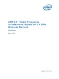
9 In this chapter we will provide descriptions and models of example short and long channels that we will use in analyzing Equalizer performance requirements. We will further subdivide the channels into two classes, full link channels and compliance channels, providing the details and roles for each in guiding the Equalizer Design process. Full Link Models Full link models represent the application environment for a Superspeed signaling interface, and include models for the PCB and package for both ends of the interface ( device and host). The two models that we are using are described in Figure 3. All models contain three differential pairs, so that the effects of crosstalk are included in the simulations, as Figure 4 illustrates.
10 All simulations in this study use the middle signal pair of the model as the victim , along with a near end crosstalk (NEXT) aggressor pair on one side and a far end crosstalk (FEXT). aggressor on the other. Figure 3. Full link channels used in this study. Figure 4. Crosstalk contributors. 3. USB Superspeed Equalizer Design Guidelines The transmission line models for printed circuit boards and packages are based on 85 15% differential impedance, and include both microstrip and stripline structures. The models for the cables are 90 7%. Impedance variation is incorporated into the full channel models. Note that the host PCB includes both stripline and microstrip routing, based on a 6-layer board stack-up.