Transcription of USER´S MANUAL HAKI STAIR TOWER
1 USER S MANUAL haki AB 2018 haki STAIR TOWER2 Copyright haki AB, 2018 The reproduct ion of text and pictures/illustrat ions wit hout haki s permission is prohibited. Important informationHAKI s product liability and user s manuals apply only to scaffolds that are entirely composed of components that have been made and supplied by haki . haki s type examination certificate applies only to scaffolds consisting of materials, dimensions and design in accordance with those specified in the documentation upon which this certificate is s scaffold systems must not be erected using components of makes other than haki or be connected to scaffolds of makes other than haki . In such cases, a special study of load-bearing capacity must be carried out. However, haki has no objection to the customary addition of scaffold tubes and approved couplers to the scaffold. Adding components from different suppliers may invalidate the insurance user s MANUAL is based on a minimum of 2 competent erectors wearing work restrain Twin Tool lanyards of fixed length of 800 mm(including Fittings).
2 This user s MANUAL is to be used in conjunction with haki training user s MANUAL should be provided to the user together with the reserves the right to make technical modifications on a continual basis. The latest versions of haki user s manuals can be downloaded from our website, For scaffold structures that are not covered by this user s MANUAL , please contact haki s technical department. Forces and dimensions 1000 N = 1 kN ~ 100 kg 10 N ~ 1 kgAll measurements in mmHAKI colour codeHorizontals and diagonals are marked with their nominal sizes (bay sizes) and a colour code. The marking is a useful means of identification when erecting and handling the scaffold material. 564 1050 1964 3050 700 1250 2050 3650 770 1550 2500 4050 1010 1655 2550 3 Following examination by the SP Technical Research Institute of Sweden, the haki STAIR TOWER system has been issued with a Type Examination Certificate in accordance with the requirements of Ordinance AFS 2013:4 of the Swedish Work Environment Authority Code of Statutes and SS-EN 12810-1 Certificate No.
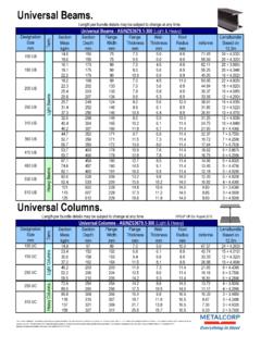
3 14 55 05. The calculations were carried out using method 4026 of the SP Technical Research Institute of haki STAIR TOWER system consists of haki Universal standards, beams, diagonal braces and guardrails and the following components that are designed specifically for STAIR towers : landings, STAIR flights, handrails, toeboards, etc. STAIR towers are erected with bay widths of 1655 mm and bay lengths of 3050 mm and with 2000, 1500 or 1000 mm between and LBL beams can be used as both ledger beams and STAIR TOWER can be erected both as an independent entity or integrated into a for the haki STAIR TOWER system are hot-dip INFORMATIONHAKI STAIR TowerGeneralAll components wit h t he except ion of locking catches, locking pins, etc. come permanently marked with the haki logo and the last two figures of the year ofmanufacture ( S18).All load bearing components are marked for full traceability. MarkingIMPORTANTENGAGE LOCKING CATCHES AS EACHCOMPONENT IS FIXED4 BASIC INFORMATIONS afety gateLandingSafety gateStair handrailToe boardStair flightHandrail postSingle Ledger3050mm1655mmLoad-bearing couplerGuardrail frameLedger BeamBase JackWall tieEntrance StepStandardGuardrail Frame5 LIST OF COMPONENTSNameCode/DataItem (kg)Base Jack BSAdjustable 55-570 SStandard joint wit h spigotPockets at same level 48 h pockets on one standard Pockets at same level 48 tripodAdapter tripod 60 Base jack BS beam LBLWit h spring locking catch 34 Ledger ERBWit h spring locking catch 48 Frame GFLWit h spring locking OF COMPONENTSNameCode/DataItem (kg)Safety gate with net SGFA djustable in BraceWit h wedge couplers 48 mmDS 1655 L=2235DS 3050 L= Handrail Handrail Post OF COMPONENTSNameCode/DataItem (kg)
4 STS Safety Guard Top Guard postGuardrail post SSKS for erect ionon ERB single tube beam and SS forerect ion on LB ledger jaw widt h 22 mmSSKS 22 mmSS Toeboard Entrance step OF COMPONENTSS upplementary componentsNameCode/DataItem (kg)Locking pinFor reinforcing standard joints inconnect ion wit h tensile load, STAIR TOWER is suspended orwhen lift ing STAIR pin 12 For locking STAIR flight ontolanding, when lift ing stairtower. Applies only to symmetrical STAIR accessoriesNameCode/DataItem (kg)Steel Plank SPLLK Deck ALLK Guardrail ot her accessories, see haki Component ion on safety when erect ing and dismant ling 1. Carry out local risk assessment and method statement. 2. Make sure that all lifting equipment to be used, chain hoists, lifting ropes, pulley blocks, etc., has been thoroughly tested and approved by an outhorised person in accordance with local regulations. 3. Check that tools and protective equipment are available at the worksite.
5 4. Wear appropriate personal safety equipment at all times, safety harnesses, proper independence lifelines with suitable fixings, etc. 5. When erecting and dismantling a scaffold, robust temporary decking must be used as temporary plat forms for t he scaffolders. 6. Always make sure that the safety locking devices that prevent a platform lifting off have been act ivated once a plat form has been installed. 7. Study all relevant instructions or safety directions from the manufacturers of the various scaffolds t hat are to be used. 8. Never climb up a scaffold from the outside. Always use the stairs, ladders or climbing frames that are designed to provide access to the upper decks from the inside of t he scaffold. 9. If the scaffold is to be used outdoors, erection or dismantling work must be discontinued if the weather conditions are severe. Make sure that all loose components are properly fixed before leaving the Scaffolding work must be done by competent operatives under the supervision of a competent person.
6 11. Lifting equipment must not be attached to a free-standing Beware of any overhead power lines Always observe and comply with the regulations issued by the local authorities Erectors/dismantlers should always be clipped to a single ledger or ledger beam during erection/dismantling. Reference should also be made to section Personal Safety Equipment in the Universal User Erect the first standard and fit a transom and ledger beam to beams are fitted to the lowest group of pockets on the the beams into standards and beams in order to complete the first necessary, fit a plan brace in order to ensure t hat t he STAIR TOWER is Fit the transom and ledger beams for t he second lift depending on the type of STAIR flight to be check the levels in both the transverse and longitudinal directions using a spirit level and adjust using the base the vertical diagonal braces and correct t he vert ical alignment of the , brace the STAIR TOWER vertically using guardrail erecting the STAIR TOWER , check and flatten out the ground.
7 The ground must not besubject to uneven settlement. The ground s bearing capacity may be improved with the help of sole A C B E F D A B GERECTION3. Install the first landing A so that the hooks rest on the ledger on an entrance step for easy access to t he lowest 3050 guardrail frames at the lowest B should always be fitted every half metre next to m STAIR flights. A 3050 single ledger can replace a 3050 guardrail the second lift with guardrail frames in bot h t he transverse and longitudinal direction. 4. Stand on an erection platform or Steel Decks and install the second landing a STAIR flight C into the pockets of the a safety gate D on the lowest landing and a handrail post E on the next level and lock them using locking a handrail F and lock it. From behind the handrail, install a top guard frame toeboards at the lowest t he STAIR TOWER to t he wall using the STAIR TOWER to structure using tube with load bearing couplers through both The STAIR flight should be locked in the landing using locking pins(2 per flight).
8 For traditional STAIR TOWER , in the event of ant icipated excessive wind conditions, it is recommended that the flights are secured (at the outboard top edge) by the use of a suitable, disposable strap. Lift up the erection platforms to the next level and install t he next set of standards, transoms and ledger beams for t he t hird Install guardrail frames to next lift using AGR From the erection platforms, install the next landing. Remove the top guard frame. Install a STAIR flight, hand-rail post and handrail. Install all t he toeboards, top guard frame and Cont inue erect ion up to t he desired height as set out approved lifting equipment for transporting exits on the long side of intermediate lifts, guardrail frames 3050 arereplaced by 2357 or 2210 guardrail frames installed wit h t he aid of a guardrail the top lift, guardrail frames are installed in bot h t he transverse and longitudinal directions as well as toeboards and a safety gate. At exits on the long side, a 2357 guardrail frame or 2210 guardrail frame is installed, with the aid of a guardrail post if 1.
9 Do not throw or drop materials to the ground. This may damage the material or cause personal injury. The materials must be lowered down to the ground by means of ropes or slings or passed down by hand. 2. If intermediate ties or tie rod tubes have been installed, they must not be removed until the dismantling process reaches the level in question. 3. Always observe and comply with the regulations published by the local authorities concerned. 4. Dismantlers should always be clipped to a single ledger or ledger beam during dismantling. 5. Reference should also be made to the section Information on safety when erecting and dismantling on page 9 in this ion on safety when dismant lingDISMANTLING Symmetrical STAIR TOWER Remove all the toeboards. From behind the handrail, remove the top guard frame, the clip on post and the 2210mm guardrail two erect ion plat forms or steel decks below the top landing and a temporary 1655mm ledger beam using AGR From the erection platforms, remove t he handrail and handrail post.
10 Remove the STAIR the top guard From the erection platforms remove the top landing. Remove all the guardrail frames using AGR Remove lift and ties. Repeat same dismantling procedure until dismantling is other dismantling procedures, please contact haki s technical CONDITIONSBase jacksThe STAIR TOWER is erected on base jacks of type BS, which are adjustable between 55 and 570 greater adjustment is needed, lower the base jacks and connect the beams to the next group of means t hat it is always possible to adjust the standards so as to make the beams of length 3000 or 2000 mm are normally used in t he STAIR , 1500 mm standards may be used at t he bottom of t he scaffold in accordance wit h t he alternat ive met hod of erect ion described on page STAIR TOWER is erected using ledger beams or single ledger as ledger and transom beams with 2000 mm, 1500 or 1000 mm between the lifts, depending on the STAIR flight to be lift must be provided wit h beams on bot h t he inside and outside.