Transcription of User Guide - Elcometer
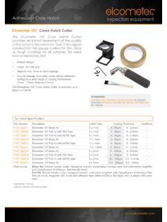
1 user GuideElcometer 107 Cross Hatch Adhesion Overview2 Box Contents3 Getting Started4 Test Procedure5 Assessing the Results6 Spares & Accessories7 Warranty Statement8 Technical the avoidance of doubt, please refer to the original English language version. Gauge Dimensions: 165 x 30 x 45mm ( x x ")Gauge Weight: 370g (13oz) is a registered trademark of Elcometer Limited, Edge Lane, Manchester, M43 6BU. United KingdomAll other trademarks acknowledged. Elcometer Limited 2009-2017. All rights reserved. No part of this document may be reproduced, transmitted, transcribed, stored (in a retrieval system or otherwise) or translated into any language, in any form or by any means (electronic, mechanical, magnetic, optical, manual or otherwise) without the prior written permission of Elcometer GAUGE OVERVIEW1 Cross Hatch Cutter Handle2 Cutter Head3 Cutter BOX CONTENTSE lcometer 107 Basic Kit contents: Elcometer 107 Cross Hatch Adhesion Tester Cross Hatch Cutter; 6 x 1mm, 6 x 2mm, 6 x 3mm, 11 x 1mm or 11 x Hexagonal Wrench.
2 Transit Case Calibration Certificate (if ordered) user GuideElcometer 107 Full Kit contents:All items listed in the Elcometer 107 Basic Kit contents, plus: Adhesive Tape; ISO or ASTM (1 roll) Cross Hatch Brush Magnifier; FITTING THE CROSS HATCH CUTTER BLADEThe Elcometer 107 is supplied with a cutter blade. Different sizes of cutting blades are available, see Section Cross Hatch Cutter Blades on page en-8, all of which fit the adhesion fit a cutter:1 Use the hexagonal wrench supplied to remove the cutter securing screw by turning Remove the existing cutter (if fitted) and position the new Re-position and tighten the cutter securing CHANGING THE CUTTING EDGEEach cross hatch cutter blade has a total of 4 cutting edges, labelled 1 to a cutting edge becomes worn, simply rotate the cutting blade by 180 to use the next cutting edge on that side.
3 Repeat until both cutting edges are the cutting blade, turn over and re-fit (see Section ), to use the cutting edges on other : The ISO/JIS Standard recommends that the cuttingtool is replaced when the top of the blades has flattened to GETTING SELECTING THE CORRECT CUTTER BLADEThe cutter blade is selected based on the substrate type, coating thickness and the test method being used, see table ThicknessTest Method mmilsASTM(Metal Substrates)ISO/JIS(Hard Substrates)ISO/JIS(Soft Substrates)0 - 500 - 211 x 1mm50 - 1252 - 56 x 2mm--0 - 60--6 x 1mm6 x 2mm61 - 120--6 x 2mm6 x 2mm 121 - 250--6 x 3mm6 x 3mm4 TEST PROCEDUREThe Elcometer 107 can be used in accordance with ISO/JIS and ASTM Standards.
4 The test procedure is dependent on the standard being BEFORE YOU START1 Select and fit the appropriate cutter blade for the test method - see Sections & on page Select the correct adhesive tape - see Section on page TEST PROCEDURE: ISO/JIS1 Place the cutting edge on the Press down gently and pull the adhesion tester towards you in one steady movement to make a series of parallel cuts approximately 20mm long. Apply sufficient pressure to ensure you cut right through the coating to the surface of the substrate. If the substrate is wood or similar, make cuts at a 45 angle to the direction of the Place the cutting edge on the sample at a 90 angle to the first cut and repeat Step 2 to create a lattice pattern on the Brush the sample lightly several times, forward and backwards along the diagonals of the lattice, to remove debris.
5 A brush is supplied as standard with the Elcometer 07 Full Kit and can also be 1purchased as an optional accessory, see Section Miscellaneous Spares & on page Inspect the sample to ensure that the cuts have penetrated all the way through the the substrate is soft, jump to Step 10. If the substrate is hard or wood, proceed to Step Remove and discard two complete turns of adhesive tape. Remove an additional length of tape at a steady rate and cut a piece approximately 75mm from this Centre the cut piece of tape over the lattice and smooth into place using a finger. Rub the tape firmly using a finger nail or finger tip to ensure good adhesion between the tape and the Within 5 minutes of applying the tape, remove the tape by pulling in a single smooth action taking approximately to 1 seconds at an angle of 60 to the To maintain a permanent record of the test, retain the tape by applying it to a transparent Assess the coating adhesion by viewing the lattice of cuts in good light.
6 If agreed, use an eye glass to aid viewing. Compare the lattice of cuts with the ISO/JIS standards table shown in Section 5 Assessing the Results on page en-7. A magnifier is supplied as standard with the Elcometer 107 Full Kit and can also be purchased as an optional accessory, see Section Miscellaneous Spares & Accessories on page : Consult the relevant Standard for full details of the test TEST PROCEDURE (continued)7860 TEST PROCEDURE: ASTM1 Place the cutting edge on the Press down gently and pull the adhesion tester towards you in one steady movement to make a series of parallel cuts approximately 20mm long. Apply sufficient pressure to ensure you cut right through the coating to the surface of the Place the cutting edge on the sample at a 90 angle to the first cut and repeat Step 2 to create a lattice pattern on the Brush the sample lightly to remove detached flakes or ribbons of coating.
7 A brush is supplied as standard with the Elcometer Kit and can also be 107 Fullpurchased as an optional accessory, see Section Miscellaneous Spares & on page Inspect the sample to ensure that the cuts have penetrated all the way through the Remove and discard two complete turns of adhesive tape. Remove an additional length of tape at a steady rate and cut a piece approximately 75mm from this Centre the cut piece of tape over the lattice and smooth into place using a finger. Rub the tape firmly using an eraser on the end of a pencil to ensure good adhesion between the tape and the TEST PROCEDURE (continued) Within 90 seconds ( 30 seconds) of applying the tape, remove the tape by pulling in a single smooth action at an angle of 180 to the coating Assess the coating adhesion by viewing the lattice of cuts using an illuminated magnifier.
8 Compare the lattice of cuts with the ASTM standards table shown in Section 5 Assessing the Results on page : Consult the relevant Standard for full details of the test TEST PROCEDURE (continued)8180 5 ASSESSING THE RESULTSThe ISO/JIS and ASTM classifications are reproduced in the table below however, we recommend obtaining a copy of the latest version of these AppearanceDescriptionClassi cationMinimum RemovalMaximum RemovalISO/JISASTMThe edges of the cuts are completely smooth; none of the squares of the lattice is of akes of the coating at the intersections of the cuts. A cross cut area not greater than 5% is coating has aked along the edges and/or at the intersections of the cuts.
9 A cross cut area greater than 5%, but not greater than 15% is coating has aked along the edges of the cuts partly or wholly in large ribbons, and/or it has aked partly or wholly on different parts of the squares. A cross cut area greater than 15%, but not greater than 35%, is ASSESSING THE RESULTS (continued)Example AppearanceDescriptionClassi cationMinimum RemovalMaximum RemovalISO/JISASTMThe coating has aked along the edges of the cuts in large ribbons and/or some squares have detached partly or wholly. A cross cut area greater than 35%, but not greater than 65%, is degree of aking that cannot be classi ed even by classi cation 4 or 1B50B6 SPARES & CUTTER BLADESThe Elcometer 107 is supplied complete with a cutter blade.
10 Various cutting blades are available for different substrate types and coating thicknesses, for use in accordance with different test methods and International Standards. Cutter blades are interchangeable and are available with or without a calibration certificate. Cutter BladeSuitable forTest MethodPart NumberISO/JISASTMASU ncerti edCerti ed6 x 1mm T99913700-1T99913700-1C6 x 2mm T99913700-4T99913700-4C6 x 3mm T99913700-5T99913700-5C11 x 1mm T99913700-2T99913700-2C11 x ADHESIVE TAPEE lcometer 107 Full Kits are supplied with one roll of tape. Tape is not supplied with basic suitable for use with ISO/JIS and ASTM test methods is available to purchase as a single roll or two roll pack, using the part numbers forTest MethodPart NumberISO/JISASTM1 Roll2 RollsAdhesive Tape K0001539M002T9999358-Adhesive Tape K0001539M001T9998894-6 SPARES & ACCESSORIES (continued) MISCELLANEOUS SPARES & ACCESSORIESThe following spares and accessories are available to purchase from Elcometer or your local Elcometer Part NumberaCross Hatch Brush T99913357aMagnifier (x6)