Transcription of USER MANUAL 3800 Gateway U9922-G38 (P/N: 40995G-01)
1 19541P-43 (09-12) 2012 DAVID CLARK COMPANY INCORPORATED user MANUAL 3800 Gateway U9922-G38 (P/N: 40995G-01) 19541P-43 (09-12) 1 of 9 CCaauuttiioonnss aanndd WWaarrnniinnggss READ AND SAVE THESE INSTRUCTIONS. Follow the instructions in this installation MANUAL . These instructions must be followed to avoid damage to this product and associated equipment. Product operation and reliability depends on proper usage. DO NOT INSTALL ANY DAVID CLARK COMPANY PRODUCT THAT APPEARS DAMAGED. Upon unpacking your David Clark product, inspect the contents for shipping damage. If damage is apparent, immediately file a claim with the carrier and notify your David Clark product supplier. ELECTRICAL HAZARD - Disconnect electrical power when making any internal adjustments or repairs. All repairs should be performed by a representative or authorized agent of the David Clark Company.
2 STATIC HAZARD - Static electricity can damage components. Therefore, be sure to ground yourself before opening or installing components. LI-POLYMER - This product is used with Li-Polymer batteries. Do not incinerate, disassemble, short circuit, or expose the battery to high temperatures. Battery must be disposed of properly in accordance with local regulations. 19541P-43 (09-12) 2 of 9 OOvveerrvviieeww The U9922-G38 (40995G-01) 3800 Gateway is a fixed-mounted wireless communication device that when used in conjunction with one or more U9910-BSW (40992G-01), U9912-BSW (40992G-02), or U9913-BSW (40992G-07) Wireless Belt Stations becomes part of a wireless intercom system. The U9922-G38 provides communication for up to four users as well as an interface to an existing David Clark Model 3800 wired intercom system. Additionally, the U9922-G38 can be used as a stand-alone wireless intercom Gateway with two-way radio interface.
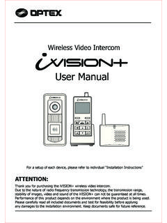
3 Up to four U9922-G38 gateways can be connected for up to 16 wireless users on one system by using the U9925-GEM (40995G-03) Gateway Expansion Module. (See U9925-GEM user MANUAL for details.) RadioInputStatus LEDVOLUMELINKA ntennaSystemInputR Figure 1: Overview of Gateway 19541P-43 (09-12) 3 of 9 IInnssttaallllaattiioonn Intercom Interface The U9922-G38 can be configured in one of three ways: 3800 Interface, Stand-alone, and Expansion Module. 3800 Interface This configuration adds wireless capability to an existing 3800 wired intercom system and can replace a U3811 or U3815 radio interface module (see 3800 system documentation for further details.) In this way, all wired and wireless users may communicate with each other as well as talk over and listen to a two-way radio. A C38-xx system cable and optional C3821 radio interface cable are required for this configuration.
4 Stand-alone Stand-alone configuration creates an ad-hoc wireless intercom and adds access to a two-way radio. This configuration does not connect to a 3800 wired intercom system. A C99-22PW (18748G-24) power cable and optional C3821 radio interface cable are required for this configuration. Expansion Module Expansion Module configuration allows up to 16 wireless users to communicate. A U9925-GEM (40995G-03) Gateway Expansion Module is required along with a C99-22MS interface cable for each U9922-G38 Gateway to be used and one C98-20PW power cable. In this configuration, if a two-way radio is used, it must be connected to the radio input on each Gateway . Antenna The U9922-G38 has two external antenna connections and is supplied with one whip style antenna. In most applications a single whip antenna is sufficient. However the optional remote antenna kit (P/N: 40688G-93 for mag-mount, 40688G-96 for permanent install) is available should more range be desired.
5 In this case, we recommend keeping one whip antenna connected directly to the U9922-G38 and routing the remote antenna somewhere else (such as on the roof of a vehicle). Choose an open, clear location for the remote antenna and route the coaxial cable away from any busy areas, preferably behind panels or in conduits. This device has been designed to operate with the antennas listed below, and having a maximum gain of 3 dB. Antennas not included in this list or having a gain greater than 3 dB are strictly prohibited for use with this device. The required antenna impedance is 50 ohms. Acceptable antennas for use with this product: Whip Antenna (P/N: 40688G-92) Remote Antenna Kit, Mag-Mount (P/N: 40688G-93) Remote Antenna Kit, Permanent (P/N: 40688G-96) 19541P-43 (09-12) 4 of 9 LLiinnkkiinngg Before a belt station and a Gateway can be connected, they must first be linked.
6 As a security measure, the close-link feature requires devices to be in proximity of about 1 to 3 ft ( to ) in order to successfully link. This ensures that the units are not inadvertently linked with other units on the premises. Linking procedure: 1. Ensure units are within 1 to 3 ft ( to ) of each other. 2. Simultaneously (within 1-2 sec) press and release the LINK button on the U9922-G38 and the LINK/PTT button on the belt station to link with. 3. Amber LED s will flash quickly on both devices. A momentary red LED indicates a successful close-link. 4. Upon successful link the U9922-G38 will attempt to establish a connection with the belt station. 5. Upon successfully establishing connection the LED on the Gateway will flash a green pattern corresponding to the number of belt stations connected. Tip: Once linked, the devices will not need to be linked again unless they are purged (see Purging).
7 Each belt station is able to be linked to only one Gateway at a time. A Gateway can have up to six belt stations linked and be connected to four of those six at one time. SSttaattuuss IInnddiiccaattiioonnss The LINK button has a multi-color LED in the center which serves as a status indication for the Gateway . Table 1 below lists these states. Table 1: LED Status Indications LED Color Blink Rate Status Red Solid Initializing/power up Red Once Connection Dropped Red Once Connection Established Red Any Low battery (approx. 1 hr remaining) Orange Slow Idle/Disconnected Orange Fast Linking/Connection in Progress Orange Solid PTT asserted Green Slow Connected (pattern indicates number of belt stations connected) 19541P-43 (09-12) 5 of 9 OOppeerraattiioonn Communication All connected belt stations will be able to communicate with each other through the U9922-G38 while in range (and per the VOX settings on each VOX belt station.)
8 Additionally, all belt station users will have communication over the intercom. If a two-way radio is installed to the U9922-G38 , pressing the PTT button on a VOX belt station will allow the user to transmit over the system s two-way radio. Pressing the PTT overrides the VOX setting on a VOX belt station. Multiple belt station users may PTT and thus speak over the two-way radio simultaneously. For more information consult the user MANUAL for the belt station. Tip: Wireless users who are not pressing PTT while another wireless user is pressing PTT will not be heard on the wired intercom while the PTT remains pressed. Intercom Level Adjustment Audio levels can vary between intercoms, mainly due to the system level setting on the wired intercom. To compensate for this, the U9922-G38 has the ability to adjust its receive level from the intercom using the Volume knob (see Figure 1).
9 Turning this knob will increase or decrease the audio level coming from the wired intercom into the Gateway . Perform this adjustment to obtain optimum performance. Intercom Level Adjustment Procedure 1. Connect at least one belt station to the U9922-G38 Gateway and ensure sidetone is present (see belt station user MANUAL ). 2. Begin speaking and slowly turn the Volume knob on the U9922-G38 clockwise until you hear an echo of your own voice. 3. Continue speaking and turn the Volume knob counter-clockwise until the echo stops. 4. You may wish to verify communication with someone hard-wired to the intercom. Radio Level Adjustment Audio levels to and from a two-way radio can also vary between radio models and manufacturers. To adjust the U9922-G38 for a particular radio, follow the procedures below. 19541P-43 (09-12) 6 of 9 Radio Transmit Level Adjustment Procedure Note: A radio service monitor is recommended for this adjustment.
10 1. Connect at least one belt station to the U9922-G38 Gateway and ensure sidetone is present (see belt station user MANUAL ). 2. Open the cover of the U9922-G38 and find the large silver knob. 3. Press and hold the PTT and speak clearly and loudly into the microphone. 4. Slowly turn the knob until the radio service monitor reads deviation. a. Clockwise to increase level; counter-clockwise to decrease Radio Receive Level Adjustment Procedure 1. Connect at least one belt station to the U9922-G38 Gateway and ensure side-tone is present (see belt station user MANUAL ). 2. Open the cover of the U9922-G38 and find the large silver knob. 3. Tune the radio to a continuous transmission (such as NWS) or transmit a test signal from another radio. 4. Adjust the volume control on the radio to a level slightly higher than typical. 5. Slowly turn the knob until you hear a loud and clear signal on the wireless intercom.