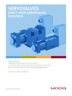
Transcription of User Manual 'D633A Series' (CA80942-001; Version …
1 DIRECT DRIVE SERVOVALVES SIZE 03 (NG6)Original user Manual ( ca80942 -001; Version , 12/08) user MANUALD633-A series Moog GmbH user Manual " d633 -A series " ( ca80942 -001; Version , 12/08) ACopyright 2008 Moog GmbH Hanns-Klemm-Stra e 2871034 B blingenGermanyAll rights reserved. No part of this user Manual may be reproduced in any form (print, photocopies, microfilm, or by any othermeans) or edited, duplicated, or distributed with electronic systems without our prior written consent. Offenders will be held liable for the payment of to change without notice. Telephone: +49 7031 622-0 Fax:+49 7031 Internet: Table of Contents Moog GmbH user Manual " d633 -A series " ( ca80942 -001; Version , 12/08) iTable of ContentsCopyright .. AList of Tables ..vList of Figures .. vi1 General Information .. Notes on the user Validity and subject to change without Completeness.
2 Storage location .. Typographical Supplementing documents .. Manufacturer s Registered Warranty and liability .. 42 Safety .. Intended operation .. Handling in accordance with safety Responsibilities .. Selection and qualification of personnel .. Structural modifications .. Occupational safety and health .. General safety Pressure limitation .. 103 Product Description .. Function and mode of Representative depiction of the valve .. Permanent magnet linear force Signal Safety function/fail-safe .. Mechanical fail-safe functions .. Valves with fail-safe function F, D or M .. Mechanical fail-safe Fail-safe Bushing-spool Restarting the Hydraulics .. Open-loop flow control (Q-control) .. Valve configurations and hydraulic symbols .. 4-way and 3-way operation .. 2-way and 2x2-way operation .. Leakage port Y .. Activation .. 18 Table of Contents Moog GmbH user Manual " d633 -A series " ( ca80942 -001; Version , 12/08) Nameplate.
3 Model number .. Type Designation .. Valve Version identification .. Rated flow identification .. Maximum pressure identification .. Bushing-spool Linear force motor identification .. Fail-safe Sealing material Valve connector Command signal identification .. Data matrix code ..234 Technical Data .. General technical data .. Hydraulic data .. Static and dynamic data .. Electrical data .. 275 Characteristic Curves .. Dependency of flow and pressure drop .. Flow signal characteristic curve .. Spool stroke signal characteristic curve .. Pressure signal characteristic curve .. Step response and frequency response .. 316 Transportation and Unpacking/checking a delivery .. Scope of delivery of the valve .. Storage .. 347 Mounting and Connection to the Hydraulic System .. Dimensions (installation drawings) .. Mounting Surface Mounting pattern of mounting Mounting the valves.
4 Tools and materials Specification for installation 398 Electrical Connection .. Wiring .. Tools and materials Electrical connection of the valves .. Valve connector X1 .. M12 valve connector MIL valve connector Grounding screw .. 44 Table of Contents Moog GmbH user Manual " d633 -A series " ( ca80942 -001; Version , 12/08) iii9 Start-up of the valves .. Filling and flushing the hydraulic system .. Start-up of the hydraulic Venting the hydraulic system .. 4910 Operation .. Preparations for operation .. Operation of the valve .. Shutting down the valve .. 5311 Service .. Removing the valves .. Tools and materials Maintenance .. Checking and replacing the port Tools and materials required .. Checking and replacing the O-rings .. Troubleshooting .. Leak at the valve connecting surface .. Leak at the linear force motor screw plug.
5 No hydraulic response by the valve .. Instability of the external control loop .. Repair .. Contact persons for repairs .. 6112 Disposal ..6313 Accessories and Spare Parts .. Accessories .. Spare parts .. 6614 Abbreviations, symbols and identification letters .. Additional Moog publications .. Quoted standards .. DIN .. DIN EN .. DIN EN ISO .. EN .. IEC .. ISO .. MIL .. Quoted directives .. 78 Table of Contents Moog GmbH user Manual " d633 -A series " ( ca80942 -001; Version , 12/08) ivFor your of Tables Moog GmbH user Manual " d633 -A series " ( ca80942 -001; Version , 12/08) vList of TablesTable 1: Position of the spool in the mechanical valve fail-safe state .. 14 Table 2: Fail-safe identification in the type designation .. 14 Table 3: Bushing-spool identification in the type designation.
6 15 Table 4: Y-identification in the type 17 Table 5: Valve Version identification in the type 19 Table 6: Rated flow identification in the type designation .. 20 Table 7: Maximum pressure identification in the type 20 Table 8: Bushing-spool identification in the type designation .. 21 Table 9: Linear force motor identification in the type designation ..21 Table 10: Fail-safe identification in the type designation .. 22 Table 11: Y-identification in the type 22 Table 12: Sealing material identification in the type designation .. 22 Table 13: Valve Version identification in the type 23 Table 14: Command signal identification in the type designation ..23 Table 15: General technical data .. 25 Table 16: Hydraulic data .. 26 Table 17: Static and dynamic 26 Table 18: Electrical 27 Table 19: Specification for installation screws .. 38 Table 20: 65 Table 21: Spare 66 Table 22: Abbreviations, symbols and identification letters .. 75 List of Figures Moog GmbH user Manual " d633 -A series " ( ca80942 -001; Version , 12/08) viList of FiguresFigure 1: Representative depiction of a direct drive 2: Representative depiction of a permanent magnet linear force motor.
7 12 Figure 3: 4-way operation with mechanical fail-safe function F (hydraulic symbol) .. 16 Figure 4: 3-way operation with mechanical fail-safe function F (hydraulic symbol) .. 16 Figure 5: 2-way operation with mechanical fail-safe function M (hydraulic symbol).. 17 Figure 6: 2x2-way operation with mechanical fail-safe function M (hydraulic symbol) .. 17 Figure 7: Nameplate (example).. 18 Figure 8: Flow signal characteristic curve .. 29 Figure 9: Setup for measuring the flow signal characteristic curve .. 29 Figure 10: Spool stroke signal characteristic 30 Figure 11: Pressure signal characteristic curve of the valves with zero lap .. 30 Figure 12: Setup for measuring the pressure signal characteristic curve .. 30 Figure 13: Step response of the spool 31 Figure 14: Frequency response of the spool stroke .. 31 Figure 15: Installation drawings for valves with M12 or MIL valve connector, dimensions in mm (inches).. 36 Figure 16: Mounting pattern of mounting surface as per ISO 4401-03-03-0-05, dimensions in mm (inches) 37 Figure 17: M12 valve connector X1 (circuit and pin assignment).
8 43 Figure 18: MIL valve connector X1 (circuit and pin assignment).. 43 Figure 19: Grounding screw .. 44 Figure 20: Repair quality 611 General InformationNotes on the user Manual Moog GmbH user Manual " d633 -A series " ( ca80942 -001; Version , 12/08) 11 General Notes on the user manualNotes on the user manualThis user Manual applies only to the standard models of d633 -A series contains the most important information for ensuring proper and correct oper-ation of the valves. Chapter " Intended operation", page 5 Chapter " Handling in accordance with safety requirements", page 6 The contents of this user Manual and the product-related hardware and soft-ware documentation relevant to the particular application must be read, under-stood and followed in all points by each person responsible for machine plan-ning, assembly and operation before work with and on the valves is requirement applies in particular to the safety instructions.
9 Chapter " Completeness", page 1 Chapter " Responsibilities", page 7 Chapter " Selection and qualification of personnel", page 8 Chapter " Handling in accordance with safety requirements", page 6 This user Manual has been prepared with great care in compliance with the rel-evant regulations, state-of-the-art technology and our many years of knowl-edge and experience. The full contents have been generated to the best of theauthors knowledge. However, the possibility of error remains and improvements are feel free to submit any comments about possible errors and incompleteinformation to Validity and subject to change without noticeValidity of the user Manual and subject to change without notice The information contained in this user Manual is valid and correct at the mo-ment of release of this Version of the user Manual . The Version number and re-lease date of this user Manual are indicated in the may be made to this user Manual at any time and without reasonsbeing CompletenessCompleteness of the user manualThis user Manual is only complete in conjunction with the product-related hard-ware and software documentation required for the relevant documents.
10 Chapter " Supplementing documents", page Storage locationStorage location for the user Manual This user Manual together with all of the product-related hardware and soft-ware documentation relevant to the particular application must be kept ready tohand and accessible close to the valve or the higher-level machine at all models of the valves custom-made for specific customers are notexplained in this user contact us or one of our authorized service centers for informationon these special General InformationSupplementing documents Moog GmbH user Manual " d633 -A series " ( ca80942 -001; Version , 12/08) Typographical conventionsTypographical conventions Supplementing documentsSupplementing documents The following supplementing documents are available: Application notes "Technical Note TN 353"Protective grounding and electrical shielding of hydraulic valves with integrated electronics Application notes "Technical Note TN 494"Maximum permissible lengths of electric cables for the connection of hydraulic valves with integrated electronicsDANGERI dentifies safety instructions which are intended to warnof immediately imminent danger to life and limb or seriousdamage to to comply with these safety instructions will inevi-tably result in fatalities, serious personal injuries (disable-ment) or serious damage to property!
