Transcription of User Manual - RF Sampler
1 1 1 user Manual Connections and Applications Table of contents: Introduction - Identifying the Problem Connections - Making the Connections and Initial Oscilloscope Setup Application 1 - Setting & Calibrating Oscilloscope for Envelope Monitoring - SSB and AM Application 2 - Trapezoidal Pattern Linearity Signal Monitor - System Self-diagnostic Test Application 3 - Using Oscilloscope as an Instantaneous Peak Reading Power Meter Identifying the Problem: Identifying the problem: With more and more HF amateurs becoming increasingly concerned with bandwidth, the station monitor solutions model RF-D (RF Demodulator), series RF-S (Variable RF Sampler ), Splatter View and series RF-AM (AM Modulation Monitor) were created to insure that your signal remains truly distortion free and linear.
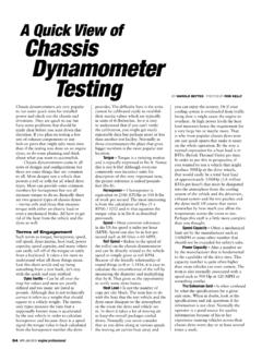
2 Providing a real time reference observation of your signal is now possible, eliminating the true root causes of splatter, buckshot, over/under modulation and nonlinearity! The possibility of your 3rd and 5th order IMD (Inter-Modulation Distortion) products will be exponentially reduced; assuring that your occupied bandwidth will be directly proportional to your transmitter's audio passband, not a mistuned nonlinear amplifier or transmitter. All oscilloscopes represent a given voltage displayed visually near the speed of light in real time, with no mechanical lag. This idea, incorporated with RF station monitoring solutions provided by the model RF-D, series RF-S, and RF-AM produces great details about your RF signal that a mere wattmeter would never be able to display!
3 Note 1: Your oscilloscope's ability to measure RF will be limited by the vertical amplifier's maximum bandwidth. A 30 MHz oscilloscope or higher is therefore recommended to easily cover the entire HF radio frequency spectrum. See a list of suggested oscilloscopes on page 23. 2 2 Making The Connection Initial Oscilloscope Setup Step 1 Making the Connections for the RF-D, RF-S series, & Splatter View series !!!WARNING: THE MODEL RF-D (RF DEMODULATOR) MUST BE CONNECTED TO THE TRANSMITTER'S OUTPUT - NEVER TO THE AMPLIFIER'S OUTPUT. FAILURE TO COMPLY WILL DESTROY THE DEMODULATOR AND VOID YOUR WARRANTY!!! To interface the "Splatter View" between the exciter, amplifier and antenna, use the high quality UHF male-to-male connectors and shielded jumper cables provided. Connect the model RF-D (RF Demodulator) directly to the output of the transmitter, via the UHF male-to-male connector provided.
4 (Choose either SO-239 connector since they are bi-directional) Connect the series RF-S (Variable RF Sampler ) directly to the output of the amplifier, via the UHF male-to-male connector provided.(Choose either SO-239 connector since they are bi-directional) Connect one BNC end of your 6 jumper cable to the BNC connector on the model RF-D (RF Demodulator) and the other end to the BNC Horizontal "X" input of your oscilloscope. Connect one BNC end of your 6 jumper cable to the BNC connector on the series RF-S (Variable RF Sampler ) and the other end to the BNC Vertical "Y" input of your oscilloscope. See the wiring illustration "Figure 1a" below. Figure 1a (1/4" TRS stereo plug required for line out application) Note 2: The RF Demodulator s 1/4" TRS jack may be used as an AM audio modulation monitor!
5 Use with stereo headphones of 63 ohms or greater, stereo line-level unbalanced input to your mixer, or stereo amplifier. 3 3 Step 1 continued Making the Connections for the RF-AM series & RF-SM To interface the series RF-AM or model RF-SM after the exciter, use the high quality UHF male-to-male connector and shielded jumper cables provided. (Choose either SO-239 connector since they are bi-directional) Connect one of the BNC end of your 6 jumper cable to the BNC connector on the series RF-AM or model RF-SM Variable RF Sampler out and the other end to the Horizontal CH 2 (Y) input of your oscilloscope. Connect one of the BNC ends of your 6 jumper cable to the BNC connector on the series RF-AM or model RF-SM External Trigger out and the other end to the External Trigger input of your oscilloscope.
6 Note: If your oscilloscope does not have an EXT BNC Trigger input (like the Tektronix 2464B) substitute the External Trigger for Channel 1 X input. See the wiring illustration "Figure 1b" below. Figure 1b Note 2: The RF Demodulator s 1/4" TRS jack may be used as an AM audio modulation monitor! Use with stereo headphones of 63 ohms or greater, stereo line-level unbalanced input to your mixer, or stereo amplifier 4 4 Step 2 Initial Oscilloscope Setup: Next, find the controls on your oscilloscope labeled "Position" for both the Horizontal CH 1 (X) and Vertical CH 2 (Y) axis. Adjust the Position controls so the horizontal sweep trace is centered vertically. Next, find the Horizontal Mode Position control. Adjust the Horizontal Position control so that the horizontal sweep trace is centered horizontally.
7 Focusing may be required. We will refer to this as establishing your "Base Line". See "Figure 2" below. Figure 2 Establishing Initial Baseline Adjustment Now, set your oscilloscope's controls for the following: o Horizontal CH 1 (X) voltage scale: 2 Volts / Div for starters o Vertical CH 2 (Y) voltage scale: 2 Volts / Div for starters o Horizontal Mode or display selector to position "A", NO DLY or NONE o Vertical Mode selector to CH 2 and "ALT" (or both if applicable) o Set both Horizontal CH 1 (X) and Vertical CH 2 (Y) channel three way position coupling selectors to "DC" (Located under the voltage selector knob) 5 5 Application #1 Step 1 Setting Oscilloscope for Envelope Monitoring: Turn time or seconds / division sweep control for 1mS for starters. Turn Trigger sweep mode to Auto, or Normal.
8 (In the Normal mode, the horizontal envelope trace will turn off when no modulation is present) o Set A Trigger coupling to "DC" (if applicable). o If using the Splatter View, select A Trigger source to "INT" or "CH 1" (or both if applicable) o If using the RF-SM or RF-AM series, select "A" Trigger source to "EXT". o Note: If your oscilloscope does not have an EXT BNC Trigger input (like the Tektronix 2464B) substitute the External Trigger for Channel 1 X input. You may need to adjust your "Slope Tune or Level" + or - knob to lock the trigger during modulation. The Trigger LED indicator will flash during modulation when level is set correctly. An added advantage of using the trigger selection is the ability to synchronize your horizontal modulation envelope sweep, regardless of changing voice or data modulated frequencies, in either SSB or AM envelope monitoring.
9 Step 2 - Calibrating Oscilloscope and Power Output for Envelope Mode: Tune up your exciter (transmitter) if necessary, and then your amplifier to its rated output within legal limit operation (1500w PEP). (The linearity tests discussed later in Application 3 will determine if you tuned your amplifier properly) With a continuous carrier established at the desired power level, adjust Vertical CH 2 (Y) voltage scale control on your oscilloscope so that the centered horizontal sweep trace expands 2 divisions above and below the baseline established in "Figure 2" on the oscilloscope's display. You should be able to make this adjustment within 10 seconds. Calibration is now complete and you can proceed to the mode you will be using (SSB or AM).
10 See "Figure 3" below. Figure 3 Oscilloscope Calibrated for Full Carrier Power Used 6 6 SSB Modulation Envelope Patterns: When using the SSB or AM modes, adjust your audio gain so that your RF envelope peaks expand to the established plus and minus 2 divisions previously calibrated for as shown in "Figure 3". A well-modulated SSB modulation envelope will look like "Figure 4" and an overmodulated SSB pattern is also represented in "Figure 5", both shown below. Figure 4 Proper SSB Voice Envelope Pattern at Full Modulation / Drive Power Figure 5 Incorrect SSB Voice Envelope Pattern Showing Overmodulation / Drive Power 7 7 AM Modulation Envelope Patterns: When using AM, first calibrate an unmodulated carrier to the plus and minus 1 division level shown in "Figure 6".