Transcription of User's Information Manual - trane.com
1 Y_C-UM-1B22-5335-2 LibraryService LiteratureProduct SectionUnitaryProductRooftop Lt. TypeUser's ManualSequence1 BDateMarch 2003 File 3/03 SupersedesY_C-UM-1B 9/02 Combination Cooling/Gas Heat Package Units If the informationin this Manual is not followed exactly, a fire orexplosion may result causing propertydamage, personal injury or loss of Do not store or use gasoline or other flammable vaporsand liquids in the vicinity of this or any other WHAT TO DO IF YOU SMELL GASDo not try to light any not touch any electrical not use any phone in your call your gas supplier from aneighbors's phone. Follow the gas supplier's you can not reach your gas supplier, call thefire Installation and service must be performed by a qualified installer, service agency or the gas supplier. Do not use thisfurnace if any part has been under call a qualified service technicanto inspect the furnace and to replace any partor the control system and any gas controlwhich has been under water.
2 Shouldoverheating occur, or the gas supply fail toshut off, shut off the gas valve to the furnacebefore shutting off the electrical *, YSC048A*, YSC060A*,YSC072A*, YSC090A*, YSC092A*,YSC102A*, YSC120A*YHC036A*, YHC048A*, YHC060A*,YHC072A*, YHC092A*, YHC102A*,YHC120A* user 'sInformationManual Customer Property: Containswiring and service informa-tion. Please retainModels :2 General InformationOverviewYour combination gas heating/electric cooling unit is de-signed to comfort condition all year long with safe, efficient,trouble free operation. It is important that you understandhow to operate and maintain your unit to keep it operatingsafely and efficiently. This Manual will acquaint you withthese important procedures. Familiarize yourself with thismanual and store it in a convenient location for future additions, changes or conversions required in order forthe unit to satisfactorily meet the application needs shouldbe made by a qualified product distributor or local servicedealer, using factory specified and approved parts.
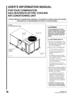
3 See fig-ure 1 for component these instructions at all times:1. Never perform any maintenance procedures until theelectrical power to the unit is turned Never perform any maintenance procedures until the gasvalve is the gas supply line is turned Never remove any panels from the unit while it is Never remove panels or parts from the unit that are notdiscussed in this Never cover the unit since it is designed to operate unit is of complex design. To ensure that it performssafely and gives long lasting services, some of the mainte-nance work must be performed by a qualified service a service person is referred to in this Manual it is de-scribing a service technician that has had special training ora number of years experience in servicing this type ofequipment. It is your responsibility to select a qualified ser-vice company that can provide a service person of this thermostats are delicate temperature sensing con-trols. Their main function is to energize and de-energize theheating or cooling circuit to maintain the temperature settingyou thermostats contain a room thermometer to indicatethe approximate room temperature and a temperature scaleat the adjustment indicator to select the desired indoor airtemperature.
4 In addition, most thermostats have a selectormode switch with Heat, Off and Cool positions and a fanswitch with On and Off the switch is positioned at Off your unit will not oper-ate in either the heat or cool modes. If the selector switch isset at Heat the unit will automatically cycle on and off tomaintain the desired temperature setting. The unit will alsooperate automatically when the selector switch is positionedat fan selector switch can be used to operate the indoorfan continuously by positioning it at On. When set to Autothe fan will only operate when required during the heatingor cooling ensure that the thermostat operates properly, it must belevel and positioned to avoid the influence of such externalheat sources and lamps, televisions or other heat FiltersFilters are to be used with this unit. Units ship from the fac-tory with filters is very important to keep the central duct system airfilters clean. Be sure to inspect them at least once eachmonth when the system is in constant operation.
5 (In newhomes, check the filters every week for the first 4 weeks.)See Table 1 for the required filter size(s).If you have disposable type filters, replace them with newfilters of the same type and size. Do not attempt to cleandisposable type filters can be cleaned by washing them witha mild detergent and water. Ensure that the filters arethoroughly dry before reinstalling them in the unit (or ductsystem).Note: It may be necessary to replace permanentfilters annually if washing fails to clean the filter, orif the filter shows signs of deterioration. Be sure touse the same type and size as was SystemHeating Cycle OperationYour unit's heating system has a solid-state electronic igni-tion control that lights the furnace burners each time thethermostat calls for heat. At the end of each heating cyclethe furnace burners are extinguished. This type of system iscalled Direct Spark Ignition (DSI).A normal heating cycle begins when the air temperaturedrops below the thermostat setting.
6 The thermostat then en-ergizes the heating electrical circuit that starts and controlsthe furnace burners. Shortly after the burners ignite the in-door fan starts and circulates warm air through the condi-tioned the air temperature rises to the thermostat setting thethermostat de-energizes the heating electrical circuit, whichin turn extinguishes the burners. The indoor fan continuesto circulate warm air until most of the heat is removed fromthe unit's combustion ControlsYour unit is equipped with an automatic reset safety limitcontrol to prevent overheating. When this control opens, itshuts down the heating electrical circuit until the unit coolsdown sufficiently. Inadequate airflow ( , caused by dirtyfilters or defective fan motor) may cause the unit to cycle onand off as the limit trips and automatically resets. If you sus-pect that the unit is cycling on it's limit control, immediatelycontact a service person for flames from the burner are not properly drawn into theheat exchanger, a Flame Rollout Protection Control willopen causing the furnace to shut off.
7 The cause must be in-vestigated by a qualified service System Start-UpSince your unit has an automatic ignition system, it is easyto start the heating cycle at the beginning of the heatingseason. In order for the unit to operate properly and safely,the furnace needs air for both combustion and to make sure that all air openings are unobstructedand there is adequate clearance around the unit to providegood air Set the thermostat's heating adjustment lever at its low-est Move the selector switch to the Off Turn off all electric power to the This unit is equipped with an ignition device which auto-matically lights the : Never attempt to manually light the Remove the access panel that contains the following THIS PANEL TO GAINACCESS TO THE GAS VALVE6. Turn gas control knob clockwise to the "OFF : Some valves require the knob to be pushed inslightly before 1- Recommended Standard FiltersInchesMillimetersInchesMillimeter sInchesMillimetersYH,SC036*(2) 20x25x1 (2) 508x635x25 (2) 20x25x1 (2) 508x635x25 (2) 20x30x1 (2) 508x762x25YH,SC048*(2) 20x25x1 (2) 508x635x25 (2) 20x25x1 (2) 508x635x25 (2) 20x30x1 (2) 508x762x25 YSC060A1,3,4,W (2) 20x25x1 (2) 508x635x25 (2) 20x25x1 (2) 508x635x25 (2) 20x30x1 (2) 508x762x25 YHC060A1,3,4,W (2) 20x30x1 (2) 508x762x25 (2) 20x30x1 (2) 508x762x25 (2) 20x30x1 (2) 508x762x25 YSC060*D,T(2) 20x30x1 (2) 508x762x25N/AN/A(2) 20x30x1 (2) 508x762x25YH,SC072*(4) 16x25x2 (4) 406x635x50 (4) 16x25x2 (4) 406x635x50 (4) 16x25x2 (4) 406x635x50 YSC090*(4) 16x25x2 (4) 406x635x50 (4) 16x25x2 (4) 406x635x50 (4) 16x25x2 (4) 406x635x50 YSC092*(4) 16x25x2 (4) 406x635x50 (4) 16x25x2 (4) 406x635x50 (4) 16x25x2 (4) 406x635x50 YHC092*(4) 20x25x2 (4)
8 508x635x50 (4) 20x25x2 (4) 508x635x50 (4) 20x25x2 (4) 508x635x50YH,SC102*(4) 20x25x2 (4) 508x635x50 (4) 20x25x2 (4) 508x635x50 (4) 20x25x2 (4) 508x635x50YH,SC120*(4) 20x25x2 (4) 508x635x50 (4) 20x25x2 (4) 508x635x50 (4) 20x25x2 (4) 508x635x50 Filter SizeHigh HeatUnit Model NumberLow HeatFilter SizeMedium HeatFilter Size47. Wait (5) minutes to clear out any gas. If you then smellgas, STOP! Follow "For Your Safety", "What To Do IfYou Smell Gas" instructions on front page. If you do notsmell gas, go to the next Turn gas control knob counterclockwise to the ON Replace panel removed in step 4 Turn on all electric power to Set thermostat to desired temperature and move the se-lector switch to the ON position. The unit will now oper-ate If the unit will not operate, follow the instructions "ToTurn Off Gas To Unit" (under Heating System Shut-down) and call your service technician or gas Note: The unit is to be adjusted to obtainan air rise within that specified on the nameplate.
9 Heating System ShutdownTo shut down the heating system for brief periods of timesimply adjust the thermostat selector switch to the "Off" Turn Off Gas To Unit1. Set the thermostat to lowest Turn off all electric power to the unit if service is to Remove the access panel that contains the following la-bel:REMOVE THIS PANEL TO GAINACCESS TO THE GAS VALVE4. Turn gas control knob clockwise to the "OFF" Replace panel removed in step 3 above. If this is done duringthe cold weather months, provisions must betaken to prevent freeze-up of all water pipesand water Whenever your houseor building is to be vacant, arrange to havesomeone inspect your structure for propertemperature. This is very important in belowfreezing weather. If for any reason yourfurnace should fail to operate, damage such asfrozen water pipes could System MaintenanceComplete the following unit inspections and service routinesat the beginning of each heating season. To prevent injuryor death due to electrical shock or contactwith moving parts, lock unit disconnect switchin open position before servicing unit.
10 To prevent anexplosion and possible injury, death andequipment damage, do not store combustiblematerials, gasoline or other flammable vaporsand liquids near the steps should only be performed by a qualified Inspect the control panl wiring and heating controls tomake sure connections are tight and wiring insulation Turn the unit on and off at the thermostat to be sure theignition control and spark electrode are operating Turn off the gas supply with the unit operating to verfiythat the gas valves closes and that a re-ignition cycle isinitiated by the ignition Check the operation of the gas ignition Check the burner manifold manifold pressure. a 1/8 inchpipe plug is provided in the gas valve for this Visually inspect all of the unit's flue product passageways for excessive deposit build up and corrosion. Ifbuild up or corrosion is appparent, perform the neces-sary Arrange for a qualified serviceman to inspect the unit ev-ery other heating season to maintain safe and Visually check the main burner flames.