Transcription of Using GigaProbes Agilent TDR D5
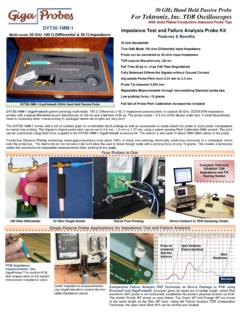
1 1 Copyright DVT Solutions, LLC 2009 Using the GigaProbes 30 Ghz TDR Hand Probes With the Agilent 86100C DCA J mainframe 54754A TDR module Perform Single Ended or Differential Impedance Measurements and Extract Insertion and Return Loss S parameters on Giga/bit Interconnects This application note demonstrates how, Using the GigaProbes , a true multi mode 30 GHz TDR hand probe, to set up and perform Single Ended or Differential Impedance measurements and extract Insertion/Return loss S parameters from TDR/TDT measurements on a variety of Gigabit interconnects where direct connection to the Device Under Test (DUT) and the Agilent 86100C DCA J mainframe TDR modules is not practical. This document describes how to setup the probes on the DUT and calibrate the GigaProbes to the Agilent 86100C DCA J mainframe s and 54754A TDR modules. System component part numbers are provided for each measurement procedure to include test results printouts for each the following Gigabit interconnects: 50 ohm Package Testing and failure analysis : Impedance and Comparative FA analysis Technique 10G/bit Molex Ipass SAS/SATA Connector PCB: Differential and S parameter analysis SATA cable : Differential and S parameter analysis Differential Coupon Testing: Differential and S parameter analysis 2 Copyright DVT Solutions, LLC 2009 Index Page # Description 1 Introduction 2 Index 3 System Components 4 Setting TDR Reference Plane a.
2 50 ohm Single Ended TDR: Setting TDR Reference Plane at GigaProbes Probe Tips 5 50 ohm Single Ended: Setting TDR Reference Plane at cable SMA End 6 100 ohm Differential: Set TDR/T Reference Plane at cable SMA End 7 Measurement Applications a. 50 ohm Package Testing and failure analysis : Impedance and Comparative FA analysis Technique 8 10G/bit Molex Ipass SAS/SATA Connector PCB: Differential and S parameter analysis 9 SATA cable : Differential and S parameter analysis 10 Differential Coupon Testing: Differential and S parameter analysis 11 Technical References 3 Copyright DVT Solutions, LLC 2009 System Components Test Equipment System Components Used to make all Application Measurements in this Document Agilent 86100C DCA J Mainframe (2) Agilent 54754A Differential TDR modules. (Some measurements were made with the (obsolete) 54753A but this module can be replaced with the 54754A for two port TDR/T S parameter measurements) DVT Solutions, LLC : DVT30 1MM GigaProbes (set of two probes and accessories kit) DVT Solutions, LLC : DVT24 GHZ 10 Qty four (4) 12 24 Ghz SMA to SMA cables DVT Solutions, LLC : DVT2650 Qty one (1) 50 ohm SMA Male Load Agilent Part# N1020A K05 Calibration Substrate (50ohm calibrate at probe tips) The DVT Solutions, LLC SOLT KIT (#TDRSOLTKIT) was used to Calibrate the TDR reference plane to the SMA cable end in this paper.
3 The Agilent N1024A SOLT calibration kit seen below is also recommended for this calibration procedure: Agilent SOLT kit Product Number: N1024A The DVT Solutions, LLC: TDRTSLOTKIT Qty two (2) each: Female SMA Short, Load, Open, Through) Probing Solutions, Inc GP2 45 L 12AL VM Qty two (2) Probe Manipulator or Cascade Ez Probe Probing Solutions, Inc FS 2 VB Fixed Vacuum Chuck For holding Up To 2" X 2" Device Packages and Small PCB s Probing Solutions, Inc AVPLN V1 Vacuum Pump, Low Noise 45db Dimension 17" Cube (vacuum hold down for GP2 45 L 12AL VM & FS 2 VB) 4 Copyright DVT Solutions, LLC 2009 Setting TDR Reference Plane 50 ohm Single Ended TDR: Set TDR Reference Plane at GigaProbes Probe Tips 1) Connect the GigaProbes configured to 50 ohm mode (fig 1) to a SMA cable 2) Select the TDR/T setup menu on the Agilent 86100C DCA J mainframe and follow Calibration instructions (fig 2) 3) Use the Agilent Part# N1020A K05 (Fig 4) Calibration Substrate for the 50 ohm & Short measurement to establish TDR reference plane at probe tips (Fig 3).
4 Important: Use the 5x micro lens enclosed in the GigaProbes accessory kit (or equivalent) to visually verify that both probe tips are making contact so excessive force is not applied to either probe tips 4) Calibration Results: 50 ohm TDR Reference at Probe Tip The following screen displays validate the calibration as accurate. Figure 5 demonstrates no load across the probe tips and the orange arrow is the TDR reference plane marker established at the probe tip. Without a load across the probes the waveform appears to oscillate but this oscillation is eliminated when a load is applied across the probe. Several measurements were taken across the Calibration Substrate to validate measurement accuracy. Fig 1) Use 50 ohm conversion kit to short one probe tip to Twin Ax probe shield. Instructions: Fig 2) On the Agilent 86100C DCA Jmainframe menu select TDR/Tsetup. The above display willappear. Select Single Ended andfollow calibration instructions Fig 3) Use the Agilent Part# N1020A K05 Calibration Substrate for the 50 ohm &Short measurement to establish TDRreference plane at probe tipsFig 4) Agilent Part# N1020A K05 Calibration Substrate Fig 5) No load on GigaProbes tip.
5 TDR reference marker is turned on a 2nd marker the measurements are reference between thetwo markers. The Gray out sections are data outside the time basecalibration zone. The time base for this setup is 200ps and showsringing from the probe tips multi path reflections but the ringing issignificantly reduced when a lode is applied, as in Fig. 6 (SHORT), Fig. 7(75 ohm), Fig. 8 (50 ohm) & Fig. 9 (28 ohm). Fig 6) GigaProbes tip across SHORT pad. Fig 7) GigaProbes tip across 75 ohm pad. Fig 8) GigaProbes tip across 50 ohm pad. Fig 9) GigaProbes tip across 28 ohm pad. 5 Copyright DVT Solutions, LLC 2009 Setting TDR Reference Plane 50 ohm Single Ended TDR: Setting TDR Reference Plane at cable SMA End 1) Connect SMA SMA cables to Agilent 54754A Differential TDR module channel 1 (do not attach probe at this time) 2) Select the TDR/T setup menu (Fig 10) on the Agilent 86100C DCA J Mainframe, follow calibration instructions 3) Attach to the end of the SMA cable a Female SMA Load and Short contained in the SLOT kit (Fig 11) when required by the Agilent 86100C DCA J mainframe TDR reference plane calibration routine.
6 4) With the TDR reference plane completed, the reference plane is now established at the SMA end of the cable . 5) Take off the SMA adapters and connect a GigaProbes Configured to 50 ohm mode (fig 12) Calibration Results: 50 ohm TDR Reference at cable SMA End Even though the TDR calibration reference plane was established at the SMA cable end and not the probe tips, several measurements taken across the Calibration Substrate to validate measurement accuracy were better than 3%. To the established TDR reference plane, turn on marker one and set it at the probe tip when probe is not connected (Fig 13). This establishes time Zero. Turn on the 2nd marker to make impedance measurements reference to the 1st marker. Several measurements taken across the Calibration Substrate to validate measurement accuracy were better than 3%. Fig 12) Use 50 ohm conversion kit to short one probe tip to Twin Ax probe shield. Look up Fig 13) with no load on GigaProbes probe tips set a TDRreference marker (solid line) to established a TDRreference plane.
7 Turning on a 2nd marker and themeasurements are reference between the two markersMeasurements were taken to validate the accuracy asshow in Figures 14 (SHORT), Fig.) 15 (75 ohm), Fig.)16 (50ohm). Fig 14) GigaProbes tip across SHORT pad. Fig 15) GigaProbes tip across75 ohm pad. Fig 16) GigaProbes tip across 50 ohm pad. Fig 11) DVT Solutions LLCTDRSOLTKIT TDR Calibration : If averaging is being used, the user can simply depress the Clear Display button to clear the measurement (clear olderdata) to validate the measurement has stabilized. Put probes in manipulators when possible. Use the 5x micro lens enclosed in the GigaProbes accessory kit (or equivalent) to visually verify that both probe tips are making contact so excessive force is not applied to either probe tip. Fig 10) On the Agilent 86100C DCA J mainframe menu select TDR/T setup. Theabove display will appear. Select SingleEnded and follow Calibration instructions 6 Copyright DVT Solutions, LLC 2009 Setting TDR Reference Plane 100 ohm Differential TDR: Set TDR/T reference plane at cable SMA End 1.
8 Connect Four SMA SMA cables to the two Agilent 54754A Differential TDR modules (do not attach probes) 2. Select the TDR/T setup menu (Fig 15) on the Agilent 86100C DCA J mainframe, follow calibration instructions 3. When required, attach to end of the each SMA cable a Female SMA SHORT, 50 ohm LOAD from the SLOT kit (Fig 17). 4. When required connect Ch1 & Ch3 and Ch2 & Ch4 (Fig 16) Using the THROUGH adapters from the SLOT kit (Fig 17) 5. When the TDR/T reference plane is completed the reference plane is now established at the SMA end of each of the cables. 6. Take off the SMA adapters and attach both GigaProbes configured to 100 ohm mode. Calibration Results: 100 ohm TDR Reference at cable SMA End Even though the TDR calibration reference plane was established at the SMA cable end and not the probe tips, measurements taken across the calibration substrate (Fig 18) validates the impedance measurement accuracy are better than 3%.
9 To the established TDR reference plane Using markers, turn on marker one and set it at the probe tip when probe is not connected. This establishes time Zero. Turn on 2nd marker to make measurements referenced to the 1st marker as in Fig. 19. Fig 15) On the Agilent 86100C DCA J mainframe menu select TDR/T setup. Set Stimulus Mode to Differential andfollow calibration instructionsFig 17) DVT Solutions, LLC TDRSLOTKIT Qty two (2) each: Female SMA Short,Load, Open, Through). Contains optionalQty two (2) Male 50 ohm loads for TDRmodule calibration Fig 16)Connect Ch1 & Ch3 and Ch2 & Ch4 when required for the THROUGH calibration Fig 18) Measurements taken across the calibrationsubstrate validates the impedance measurementaccuracy is better than 3% Fig 19) Turn on 2ndmarker to make measurements referenced to 1stmarker. 7 Copyright DVT Solutions, LLC 2009 Measurement Applications 50 ohm Package Testing and failure analysis 1) Convert the GigaProbes to 50 ohm as in Figure 20 2) Set the TDR reference plane of the GigaProbes (at probe tip or at SMA connect end) as described in section 3.
10 3) Hand Probing Packages: Slip the Ez Grip (Fig. 22) hand hold adapter over the GigaProbes and connect the GigaProbes to the DVT24 GHZ 12 SMA SMA 12 24 GHz cable to the Agilent 54754A TDR module. 4) Using a Probe Manipulator: In this example (figure 21), the GigaProbes was installed in the GP2 45 L 12AL VM from Probing Solutions inc. or equivalent probe manipulator by removing the Ez Grip adapter and attaching the GPMMA adapter on the probe manipulator. Loosen the two cross bars on the GPMMA and push the probe forward until the 1st cross bar is over the twin SMA coupler where it attaches to the 100 ohm Twin Ax coax. Tighten down the 1st cross bar over the Twin coupler and then tighten the 2nd cross bar. Do not tighten 1st cross bar over Twin Ax coax as this may damage the probe. 5) Holding the Device Package: Put Device Package on the FS 2 VB Fixed Vacuum Chuck (Fig 21) that accommodates up to 2" X 2" Device Packages. This Chuck can also be used to secure small PCB s.