Transcription of Using PWM Output as a Digital-to-Analog …
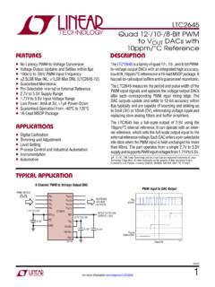
1 Application Report SPRAA88A September 2008. Using PWM Output as a Digital-to-Analog converter on a tms320f280x digital Signal Controller David M. Alter DSP Applications Semiconductor Group ABSTRACT. This application report presents a method for utilizing the on-chip pulse width modulated (PWM) signal generators on the tms320f280x family of digital signal controllers as a Digital-to-Analog converter (DAC). The method involves analog low-pass filtering the PWM signal to remove high frequency components, leaving only the low-frequency content. Theoretical and experimental results are presented to quantify the achievable bit resolution and bandwidth, which depend upon the analog low-pass filter employed, the PWM frequency, and the DSP operating frequency. When coupled with a second order passive RLC filter, the hi-resolution PWM module on the tms320f280x device is seen capable of providing greater than 9 bits of DAC resolution with 100 kHz bandwidth.
2 Alternately, 50 kHz DAC bandwidth is possible with better than 10 bits of resolution. These resolutions and bandwidths make the PWM/DAC a legitimate lower cost alternative to dedicated off-chip DACs in tms320f280x based systems.. TMS320 is a trademark of Texas Instruments, Inc. Trademarks are the property of their respective owners. SPRAA88A. Contents 1 Introduction ..4. 2 Frequency Analysis of the PWM Signal ..5. 3 D/A Resolution Issues ..6. 4 analog Low-Pass 1st Order Low-Pass 2nd Order Low-Pass Filter ..9. Higher Order Low-Pass Filters ..10. 5 Simulation of D/A Performance ..11. 6 Experimental Setup and Results ..17. Sinusoidal Output Results ..17. Step Response Results ..19. 7 Additional Issues and Possibilities ..21. HRPWM Duty Cycle Range Limitation on the Calibration ..23. 8 C-Code General Directory Structure and Filenames ..25. Additional 9 Appendix A. Derivation of Worst-case Duty Cycle.
3 29. Revision Figures Figure 1. Decomposition of a PWM Figure 2. analog Filtering of PWM Signal ..4. Figure 3. PWM Signal Time-Shifted for Even Symmetry ..5. Figure 4. Total Uncertainty in the D/A Figure 5. 1st Order Passive Low-Pass Filter Circuit ..9. Figure 6. 2nd Order Passive RC Low-Pass Filter Circuit ..10. Figure 7. 2nd Order Passive RLC Low-Pass Filter Circuit ..10. Figure 8. Magnitude Response of the analog Low-Pass Figure 9. Phase Response of analog Low-Pass Figure 10. D/A Resolution vs. PWM Frequency, Filter #1 (from Simulation) ..13. Figure 11. D/A Resolution vs. PWM Frequency, Filter #2 (from Simulation) ..13. Figure 12. D/A Resolution vs. PWM Frequency, Filter #3 (from Simulation) ..14. Figure 13. D/A Resolution vs. PWM Frequency, Filter #4 (from Simulation) ..14. Figure 14. D/A Resolution vs. PWM Frequency, Filter #5 (from Simulation) ..15. Figure 15.
4 D/A Resolution vs. PWM Frequency, Filter #6 (from Simulation) ..15. Figure 16. D/A Resolution vs. PWM Frequency, Filter #7 (from Simulation) ..16. Figure 17. Filter #5 Output of PWM Sine Figure 18. Filter #5 Step Figure 19. Theoretical Filter #5 Unit Step Response (from Simulation)..20. Figure 20. Filter #5 Output of PWM Sine Wave Showing Range Limits ..21. Figure 21. Effective Full-Scale D/A Range Using HRPWM module ..22. Figure 22. Flow of PWM/DAC Example 2 Using PWM Output as a Digital-to-Analog converter on a tms320f280x digital Signal Controller SPRAA88A. Tables Table 1. Filter Parameters used in Simulation Study ..11. Table 2. Directory Structure of Example Code ..25. Table 3. File Inventory for Example Code ..25. Using PWM Output as a Digital-to-Analog converter on a tms320f280x digital Signal Controller 3. SPRAA88A. 1 Introduction The PWM signal outputs on a TMS320F280x1 device are variable duty cycle square-waves with volt amplitude.
5 These signals can each be decomposed into a component plus a new square-wave of identical duty-cycle but with a time-average amplitude of zero. Figure 1 depicts this graphically. It will be shown in Section 2 that the amplitude of the component is directly proportional to the PWM duty cycle. = +. t t Original PWM signal Component Zero average square wave Figure 1. Decomposition of a PWM Signal The idea behind realizing Digital-to-Analog (D/A) Output from a PWM signal is to analog low-pass filter the PWM Output to remove most of the high frequency components, ideally leaving only the component. This is depicted in Figure 2. The bandwidth of the low-pass filter will essentially determine the bandwidth of the Digital-to-Analog converter . A frequency analysis of the PWM signal is given in the next section in order to provide a theoretical basis for the filtering strategy.
6 analog Low-Pass Filter t t Original PWM Signal Desired analog Output Figure 2. analog Filtering of PWM Signal 1. tms320f280x will hereafter refer specifically to TMS320F2801, TMS320F2806, TMS320F2808, and UCD9501 devices. 4 Using PWM Output as a Digital-to-Analog converter on a tms320f280x digital Signal Controller SPRAA88A. The PWM/DAC approach is not new, but performance limitations have historically confined its use to low-resolution, low-bandwidth applications. The performance of the method relates directly to the ability of the low-pass filter to remove the high-frequency components of the PWM. signal. Use a filter with too low a cut-off frequency, and DAC bandwidth suffers. Use a filter with too high a cut-off frequency or with slow stop-band rolloff, and DAC resolution suffers. These issues will be discussed in more detail later in this report, but one way to alleviate both of these problems is to increase the frequency of the PWM.
7 However, as PWM frequency increases on conventional microprocessor generated PWM, digital resolution problems begin to manifest. It will be seen in this report that the hi-resolution PWM module (HRPWM) on the tms320f280x family of digital signal controllers is able to overcome these performance limitations to a great extent and offer real-world useable DAC performance. 2 Frequency Analysis of the PWM Signal Fourier theory states that any periodic waveform can be decomposed into an infinite sum of harmonics at integer multiple frequencies of the periodic frequency. Without loss of generality, the Fourier series representation of the PWM signal can be simplified by judiciously placing the time origin so that the signal becomes an even mathematical function, as shown in Figure 3. f (t ). p p p p t T T + T T 0 T T T T. 2 2 2 2. Figure 3. PWM Signal Time-Shifted for Even Symmetry In Figure 3, p denotes the PWM duty cycle (0 p 1), and T denotes the carrier period in seconds.
8 Note that a tms320f280x controller can generate both asymmetric and symmetric PWM. This should not be confused with even symmetry, which is a mathematical property of a function. The signal depicted in Figure 3 applies equally well to either type of PWM. The Fourier series representation of an even periodic function f(t) may be computed as follows (see reference [1]): . 2n t 2n t . f (t ) = A0 + A. n =1. n cos . T . + B n sin . T . (1). where: T. f (t )dt 1. A0 = (2). 2T. T. Using PWM Output as a Digital-to-Analog converter on a tms320f280x digital Signal Controller 5. SPRAA88A. T. 2n t . f (t ) cos . 1. An = dt (3). T T . T. T. 2n t . f (t ) sin . 1. Bn = dt (4). T T . T. Let K denote the amplitude of the signal f(t) in Figure 3. One obtains the following results after performing the integrals (2) - (4): A0 = K p An = K . 1. [sin (n p ) sin (2n (1 p / 2) )] Bn = 0 (5).
9 N . The zero result for Bn is expected for an even function, and will not be discussed further here. The component A0 is seen equal to the PWM amplitude multiplied by the PWM duty cycle. This is the desired D/A Output . By selecting the proper duty cycle, any D/A Output voltage can be obtained within the range 0 to K volts. The An terms represent the amplitudes of the high frequency harmonic components of the PWM signal, which are seen to exist at integer multiples of the PWM carrier frequency 2 /T (Hz). For example, when Using 1 MHz PWM, the harmonics occur at 1 MHz, 2 MHz, 3 MHz, and so on. An ideal brick-wall low-pass filter with a cut-off at any frequency below the 1 MHz carrier frequency will completely remove the high frequency harmonics, leaving only the component. Additionally, it will allow the PWM duty cycle to be varied at frequencies up to the cut-off frequency and reflect this variation with a corresponding voltage level change in the Output .
10 Of course, one cannot build an ideal filter, and a real filter will always allow some portion of the harmonics to pass. This produces ripple in the desired Output , as was illustrated in Figure 2. 3 D/A Resolution Issues Two main sources of error affect the desired D/A Output . First, the PWM duty cycle can only be specified with finite resolution. On the tms320f280x , there are two components to this. The course resolution is directly related to the PWM carrier frequency used. For example, suppose 100 kHz PWM is desired with the PWM module driven by a 100 MHz CPU clock. The time-base of the PWM provides 1000 clock counts per cycle of PWM at which to specify the timer compare value and hence the duty cycle. When Using the standard PWM on the tms320f280x devices, this equates to just less than 10-bit resolution. In other words, the desired Output can only be specified in steps of mV ( counts).


