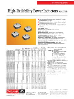
Transcription of Using Standard Transformers in Multiple Applications
1 Document 857-1 Revised 04/13/10 Creative Use of Alternate Winding ConnectionsUsing StandardTransformers inMultiple ApplicationsIntroductionMany Coilcraft Transformers were designed for optimalperformance in a specific application. Catalog informa-tion presents the Transformers based on the specifica-tions for that original application. However with a littlecreative thinking, most Transformers can be adapted toa variety of circuit uses just by considering differentconnections for the to ConsiderA transformer winding might be constructed of multiplewires intended to be connected in parallel. The usermight instead consider connecting those wires in seriesto increase the resulting inductance or turns ratio. Carefulconsideration of all the resulting variables should bemade before attempting alternate configurations. Thosevariables include: inductance value (L) dc resistance (DCR) rms current (Irms) temperature rise (due to current and resistance) peak / saturation current (Ipk or Isat) self resonant frequency (SRF) voltage / isolation between wires / safetyFor example, assume a coil winding, either primary orsecondary side, is made with two parallel (bifilar) (L)Inductance is proportional to the square of the turnswhen wound on the same core.
2 So two equal coils,wound on the same core and connected in series haveabout four times the inductance of the parallel ResistanceWhen the same two wires are connected in series, theDC resistance is fourfold (4 ) compared to the paral-lel CurrentThe rms current rating is based on temperature rise,which is related to power amount of current flowing through the series com-bination that causes the same temperature rise as theparallel combination is calculated as follows:IS2 DCR = Therefore:SP2PI DCRISIPDCRPDCRS==12 For equal windings, Irms for the series connection ishalf that of the parallel connection and yields the sametemperature CurrentSaturation of ferrite or powdered iron cores is related tothe energy storage capability of the inductor as indi-cated by the volt-time product (V t). An approximationof the volt-time product can be calculated from theequation:V = L di/dtrearranged in the form V T = L :V T is the volt-time product in volt- sL is the inductance in Hand it is assumed that:dt is approximated by T, anddi is approximated by Isat (the rated saturation currentshown on the data sheet)Since the inductance is four times as shown above, thecurrent that causes saturation is one fourth that ofthe parallel Resonant Frequency (SRF)The self resonant frequency of two bifilar-wound wiresdepends on the inductance and capacitance.
3 Whenconnected in series, the interwinding capacitance andwinding capacitance to ground may change. The effec-Document 857-2 Revised 04/13/10tive capacitance change may be small compared toinductance but should be considered. Since induc-tance is 4 , the self resonant frequency is proportionalto 1/ L C so the series SRF will be about 1/ 4 , approxi-mately half that of the parallel / Isolation / SafetyCoilcraft typically specifies isolation between wind-ings that are intended to be used separately, such aswith coupled inductors or Transformers . We do notnormally specify isolation between wires on multi-wire(bifilar, trifilar, etc.) windings designed to be connectedin wires are bifilar wound, the isolation between themwill be quite small, and not routinely tested. Therefore, it isrecommended that sufficient testing of samples be per-formed to verify a safe isolation voltage for the example discussed is a best-case simple two-wirecoil, yet it illustrates many of the variables to considerwhen Using our products in connection configurationsfor which they were not designed.
4 More complicatedwiring configurations could require additional consider-ations that are not discussed here.