Transcription of Using Strain Gauges to Detect Epoxy Debonding in …
1 Using Strain Gauges to Detect Epoxy Debonding in insulated rail Joints Daniel Peltier, Christopher P. L. Barkan, Steven Downing, and Darrell Socie University of Illinois at Urbana-Champaign, Urbana, IL, USA Summary: Track circuits are used for traffic control on a large portion of North American mainline track. These require insulated rail joints every several kilometers in order to electrically isolate sections of the rail . Such insulated joints have short service lives compared to other track components, but current methods for monitoring their condition and detecting defects are either too involved for everyday use or insufficiently ac-curate. We are researching a new system based on low-cost smart sensor technology that will enable railroads to monitor the condition of insulated joints, plan for their maintenance or replacement, respond faster to problems, and collect statistical data about their performance.
2 The system uses Strain Gauges to track the me-chanical characteristics of a joint over time. By understanding how these properties change as the joint de-grades, we can Detect and report problems in a timely manner. Index Terms: track structure, condition monitoring, sensor technology, system reliability 1. INTRODUCTION insulated rail joints are widely used throughout the North American rail network, occurring roughly every 5 km (3 miles) on almost all signaled track. These joints have shorter service lives than most other track components. Fortunately, most failures are not safety problems in and of themselves. But the magnitude of the problem, and the difficulty of obtaining good information about joint condition, makes keeping up with the necessary replacement work a challenge.
3 The result is that insulated joint failure is more disruptive to railroad operations than it would be if failure could be detected auto-matically in time to schedule joint replacement in a rational manner. This paper focuses on the devel-opment of a technique and a technology for moni-toring insulated joints that costs very little in terms of money, labor, or attention from the user. 2. insulated rail JOINTS On North American heavy-haul railways, train con-trol usually relies on various kinds of direct current (DC) track circuits to Detect the presence of a train within a control block. Adjacent circuits within the track are separated by insulated rail joints (also called simply insulated joints or IJ s), a point where two separate rail sections are held together but electrically insulated from each other.
4 Although these joints are always installed in pairs, one di-rectly across from the other, most circuits will op-erate properly when separated by a single function-ing joint , so long as the electrical resistance within that joint is sufficiently high. If both insulated joints fail, the train control logic switches into a failsafe mode, displaying stop indications for all traffic through the area and disrupting operations. Bonded insulated joint design As with any rail joint , an insulated joint is a weak spot in the track structure. While the number of joints in mainline track has been minimized by the widespread use of continuously welded rail (CWR), North American railroads have not identi-fied an acceptable alternative to track circuits with insulated joints.
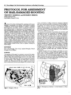
5 They have, however, migrated to-ward the use of bonded insulated joints. A bonded IJ, instead of being held together by bolts, has a layer of Epoxy to bond the joint bars directly to the rails. The Epoxy itself serves as the electrical insu-lator between the joint bars and the rails. Studies have shown that a bonded IJ is significantly stiffer (more like the welded rail surrounding it) than tra-ditional bolted designs [1]. Figure 1 shows an exploded view of a typical bonded insulated joint , including the Epoxy layer. While the assembly does have bolts, they do not have a significant effect on the action of the joint under loads. They mainly serve to provide a clamp-ing force while the Epoxy cures; after that, they act as a backup system in the event the Epoxy fails.
6 Thin insulating sleeves isolate the bolts from the web of the rail . Similarly, a fiberglass insert called an endpost ensures physical and electrical separa-tion between the ends of the two rails, but is not designed to carry loads. joint bar length, hole spac-ing, and endpost thickness are more or less stan-dardized. The thickness of the Epoxy layers and the cross section of the joint bar vary from manufac-turer to manufacturer. With recent increases in North American axle load-ings and annual tonnage, service lives of bonded IJ s have dropped substantially. Because of this, and because of improved designs and practices for other problematic track components, IJ s now have the shortest service life of any common track com-ponent in North American heavy-haul service, with the exception of high-angle rail crossings [2].
7 insulated rail joint failure and inspection Davis et al [2] describe the most typical failure of bonded insulated joints. Failure begins when the Epoxy either cracks or comes unbonded from the metal surfaces of the rail at the point of maximum shear stress, which occurs near the endpost. As the bonding fails, the deflection of the joint under pass-ing wheel loads increases. This leads to higher dy-namic loads on the support system and higher dif-ferential movement between the rails and the bars, which in turn increases Epoxy stress and hastens the Debonding . The debonded region propagates back towards the ends of the joint bar. In this fail-ure mode, a joint will usually be considered failed when the debonded region grows to an un-acceptable level.
8 Other problems that develop in a loose joint , such as broken bolts or loss of electrical resistance, may also lead to service failure. There is no generally accepted standard for what constitutes an unacceptable amount of Debonding , which may be due to the fact that there are no pub-lished studies quantifying the effect of Epoxy dam-age on serviceability. Aside from normal rail defect and geometry inspec-tions, insulated joint inspection techniques fall into two categories: visual and electrical. Problems de-tectable by visual inspection include joint bar cracks, broken bolts, plastic flow of the rail head at the end post, and problems with crossties, fasten-ers, or longitudinal restraint.
9 The inspector can also Figure 1: Exploded view of a bonded insulated joint joint bar Bolts Epoxy Rails Endpost examine the upper and lower edges of the Epoxy layer (the only part of the layer visible to the eye) to Detect the presence and estimate the size of a debonded region. Inspections are usually conducted on foot, due to the limited viewing angles available from a moving vehicle. Starting January 1, 2007, the United States Federal Railroad Administration requires an on-foot visual inspection of certain components of insulated joints on most mainline freight railroads approximately once for every 18 million gross metric tons (20 mil-lion tons) of traffic [3]. These inspections are geared towards finding joint bar cracks, and do not require an assessment of Epoxy condition.
10 Electrical inspections include various methods for testing the electrical resistance between one rail and the other. It can be difficult to perform these tests without interfering with the operation of the track circuit. Because electrical failures are de-signed to be fail-safe, electrical inspections of insu-lated joints tend to happen only when signal prob-lems or visual inspections suggest a problem. We believe that current insulated joint inspection practices are insufficient to ensure that the full service life is obtained while minimizing the likeli-hood of an operationally disruptive failure. The high number of insulated joint installations, the la-bor-intensive nature of available inspection tech-niques, and uncertainty about the extent and sig-nificance of Epoxy loss even when a joint is in-spected prevent maintenance personnel from scheduling insulated joint replacement in a timely but efficient manner.