Transcription of ValveExpert Checker Portable Service Set with Universal ...
1 ValveExpert Checker DIETZ automation 1 ValveExpert CheckerPortable Service Set with Universal Control Unit for Servo and Proportional Valveswith Integrated ElectronicsValveExpert Checker DIETZ automation 2 Featuresof the unit: The control unit ValveExpert Checker is used to control and carry out functional tests on servo andproportional valves with integral electronics and operating voltages of 15V or +24V. Simplifies commissioning and troubleshooting in hydraulic systems with servo and proportional valves. All standard servo- and proportional valves with 6+PE connectors are supported (MOOG, Parker-Hannifin, Bosch-Rexroth, Eaton, and many others). Additional control for ON/OFF pilot valve.
2 Intuitively simple and comfortable interface. Built in digital multimeters for control and feedback signals. Comfortable bright LED indications. Supports external and internal control modes. Three internal control modes are supported: +10V, +10mA, Support current (mA) and voltage (V) feedback signals. The Service case comprises a test unit as well as an optional power supply unit (+24V, 3A), connecting cables, and adapter cables. Overloadand short circuit protections. Compact and robust :Degree of protection:IP03 (use in dry area)Servovalve connector:6+PE pole, EN 175201 Part 804 Pilot valve connector: DIN EN 175301-803, form AOperating voltage(Pin A and B) VDC(full functionality) (measurement only) Pin C used as 0V for 15V power supplyCharging rate of the test load capacity (Pin A and B):3 AControl signal (Pin D and E) + + input (Pin C): Disable: : signal (Pin F) +30V +30mAMax.
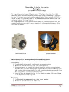
3 Load for pilot valve: (overload protected)Dimensions:470mm x 380mm x 95mmWeight: Test: EN 50 081-1EN 50 082-2EN 60 742 ValveExpert Checker DIETZ automation 3 Function description and operating instructions:Figure 1. Test unit ValveExpert test unit may only be used by persons who are familiar with the unit, the valve and the hydraulic system. When set accordingly, the unit ignores control signals that come from the system. If safety features are provided on the control side, these are deactivated. We assume no responsibility for damage caused by misuse! ValveExpert Checker DIETZ automation 4 Functional elementLabelPositionInput plug ES :Connection on the control side(CM02E14S-61P)1 Output socket PL : Connection for the pilot valve(Binder 09-0404-00-02)2 Output socket AB.
4 Connection on the valve side(TR1208 RFS1NB)3 LED indicator for control of the power supply voltageV Supply4 LED indicator for voltage mode feedback signalV indicator for current mode feedback signalmA LED indicator for feedback value7 Switch of feedback mode (mA/V) and power supply testSupply / Feedback8 LED indicator of enable signal for input plugEnable In9 LED indicator of enable signal for output socketEnable Out10 LED indicator for + +20mA control signal4-20mA11 LED indicator for +10V control signal 10V12 LED indicator for +10mA control signal 10mA13 Digital LED indicator for control value14 Switch of control mode (4-20mA, 10V, 10mA)Control15 Switch for pilot valvePilot ON / Pilot OFF16 Potentiometer for adjusting the internal command value signal (4-20mA, 10V, 10mA)-100%.
5 +100%17 Switch for Internal / External mode of controlInternal / External18 Power supply switch 15V / +24V 15V / +24V19 Enable / Disable switch for the generation of an eneble signal for the valveEnable / Disable20 Functional switch for pin C (Enable or Reference potential for actual valve value)C-Ref. / 1. Functional elements of the test unit ValveExpert Checker DIETZ automation 5 SwitchSwitch positionFunctionPower selector(19)+24 VInternal reference potential is connected to Pin supplyis +24V(Pin A). The enable signal can be generated using switch "Enable" or switched off (20). 15 VInternal reference potential is connected to Pin supply is 15V(+15V Pin A, -15V Pin B. The switch "Enable"(20) is (20)+24V operationonlyEnableSet point switch (18) in External mode-> an external enable signal applied to the valve (Pin C).)
6 Set point switch (18) in Internal mode-> enable signal for the valve is set(Pin C).DisableEnable signal output (Pin C) is connected with reference potential (0V).Set point(18)ExternalExternal command value applied to the valve via pin D and pin value from potentiometer (17) is applied to the mode(15)4-20mA-100%..+100% of the command from potentiometer (17) corresponds to + +20mA of the control signal. LED (11) is active. 10V-100%..+100% of the command from potentiometer (17) corresponds to +10V of the control signal. LED (12) is active. 10mA-100%..+100% of the command from potentiometer (17) correspondsto +10mA of the control signal. LED (13) is mode(8)V SupplyTest of the power supply voltage (V). LED (4) is signal is voltage (V).
7 LED (5) is signal is current (mA). LED (6) is of pin C(21)C C is a reference for the feedback value of the C is unused or used for enable ON/OFF(16)Pilot ONActivates the pilot valve over connector (2). 24 VDC (for +24V operation) or 30 VDC (for 15V operation) applies to the pilot valve connected to the DIN connector. LED on the DIN connector is active. Maximal current OFFD eactivates the pilot valve over the connector (2).Table 2. Functions of the control Checker DIETZ automation 6 PinValve version with operatingvoltage +24 VValve version with operatingvoltage 15 VASupply +24 VSupply +15 VBSupply ground 0 VSupply -15 VCEnable or Reference potential for actual value with 4 WRSE (Rexroth)Supply ground 0 VDPositive command valuePositive command valueENegative command valueNegative command valueFActual valueActual valuePEProtective earthProtective earthTable 3.
8 Pin assignment of the servo- or proportional valve connector (6+PE pole, EN 175201 Part 804).PinValve version with operatingvoltage +24 VValve version with operatingvoltage 15 V1 Supply +24 VSupply +15V2 Supply ground 0 VSupply -15 VPEP rotective earthProtective earthTable 4. Pin assignment of the pilot valve connector (DIN EN 175301-803, form A). ValveExpert Checker DIETZ automation 7 Power supply and cables:Figure 2. Cable to connect the test unit with a servo- or proportional 3. Cable toconnect the test unit with a pilot valve ( , max).Figure 4. Power supply unit (Input: 100 240 VAC, Output: 24 VDC, 3A).Figure 5. Connector view of the test unit ValveExpert Checker DIETZ automation 8 Dr.
9 Mikhail ShashkovDIETZ automation GmbHBrunnenstr. 5366538 NeunkirchenGermany+496821