Transcription of Vapor Compression Refrigeration Cycle
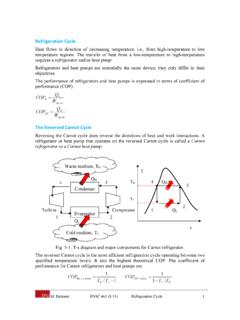
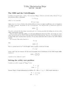
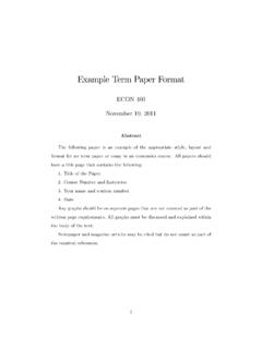
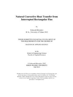
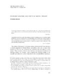
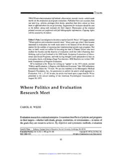
1 1 M. Bahrami ENSC 388 Experiment 2: Vapor Compression Refrigeration Cycle ENSC 388: Engineering Thermodynamics and Heat Transfer Experiment 2: Vapor Compression Refrigeration Cycle Objective Determining the coefficient of performance of a vapour Compression Refrigeration Cycle . Apparatus Figure 1 shows the experimental setup in details. Key components in the Refrigeration system are a compressor, a condenser, an evaporator and an expansion valve. The compressor unit shown in Fig. 2 comprises an encapsulated, fully hermetic reciprocating compressor with an integrated drive motor. Such compressors are used in regular refrigerators. The condenser is a glass container with a cooling coil through which water flows (see Fig. 3a). The gaseous refrigerant is pumped into the container by the compressor, here it condenses and collects in the bottom of the container.
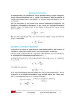
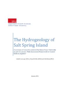
2 Heat is drawn off via the water circulating in cooling coil in the container. The evaporator shown in Fig. 3b, similar to the condenser, includes a glass container and a copper coil through which water flows. In this case, the water is not used for cooling; conversely, it generates the cooling load. The refrigerant expands in the evaporator and changes from the liquid to Vapor . The system has an expansion valve which is a float valve. Schematic of the expansion valve is shown in Fig. 4. Once the refrigerant collecting in the condenser reaches a certain level, the float (1) lifts the needle (2) from its seat, and opens the connection to the evaporator. The injection of the refrigerant into the evaporator is controlled by the expansion valve. When the system is started, the air in the system has to be released using the bleed valve. For this purpose the valve (item 20 in Fig.)
3 1) is opened several times for a few seconds after the compressor is started, until the clearly detectable odour of escaping gas indicates that there is no more air in the system. 2 M. Bahrami ENSC 388 Experiment 2: Vapor Compression Refrigeration Cycle 1 Table Support 12 Flow meter, Hot Water 2 Water Connections 13 Sight Glass 3 Temperature Measurement Point 14 Evaporator 4 Condenser 15 Pressure Display, Evaporator 5 Expansion Valve 16 Power meter, Compressor 6 Hand Valve 17 Switchable Temperature Display 7 ON-OFF Switch, Compressor 18 Flow meter, Refrigerant 8 Compressor 19 Pressure Display, Condenser 9 Filling Connection 20 Bleed Valve 10 Emergency Stop Button 21 Pressostat 11 Master Switch 22 Flow meter, Cooling Water Figure 1- Components of experimental apparatus Figure 2- Compressor unit 3 M.
4 Bahrami ENSC 388 Experiment 2: Vapor Compression Refrigeration Cycle (a) (b) Figure 3- a) Condenser and b) Evaporator of the system. Figure 4- Schematics of the expansion valve. The system is equipped with 8 thermometers. The positions of the measuring points are marked with their numbers on the front panel of the system; these numbers correspond to the following points: = Cold water inlet, condenser = Cold water outlet, condenser = Hot water inlet, evaporator = Hot water outlet, evaporator = Mean temperature, evaporator = Refrigerant temperature, outlet of compressor = Mean temperature, condenser = Temperature after expansion valve The measured data collected during the operation of the system enables one to calculate the thermal characteristics of the system to be calculated.
5 Filling and draining the system The system is to be filled until the glass container for the evaporator is half full (Fig. 1). The hand valves 1 - 3 are open during the filling process, hand valve 4 is closed. 4 M. Bahrami ENSC 388 Experiment 2: Vapor Compression Refrigeration Cycle Fit suitable hose to the filling connection (9) and insert into the container in which the refrigerant is supplied such that refrigerant can be drawn out. Start the compressor, a partial vacuum is formed in the evaporator such that the refrigerant is drawn out of the container Continue filling process until the evaporator is half full with the liquid phase of the refrigerant Close the hand valve 2, remove the hose Switch off the compressor The compressor is filled with oil on assembly in the factory; this filling is sufficient for its lifetime. Due to the fully hermetic construction, no more oil can be added during later operation.
6 However, during its operation oil droplets enters the refrigerant circuit. When the system is switched off, the majority of the refrigerant and some oil gather in the evaporator. The oil is returned in the following way: Hand valves 2 and 3 must be closed Hand valves 1 and 4 must be open Switch on compressor, the liquid is drawn from the compressor through the capillary tube to the compressor and from there pumped to the condenser When the contents of the container have been drawn out, stop the process, for this purpose close valve 4 and open valve 3; in this way the system is again in normal operation For draining the system Switch off the compressor Fit the hose to the filling connection and place it in the container Open all hand valves except valve 4 Open bleed valve (item 20 in Fig. 1), the refrigerant slowly returns to the container Theory The basis of Refrigeration systems is a thermodynamic Cycle working between two different temperature sources.
7 In this Cycle a refrigerant ( R134a) passes through various changes of state in a defined sequence and returns to its initial state. A refrigerator is a machine that removes heat from a low temperature region. Since energy cannot be destroyed, the heat taken in at a low temperature must be dissipated to the surroundings. The Second Law of Thermodynamics states that heat will not pass from a cold region to a warm one without spending energy or work. Therefore, a refrigerator requires energy input for its operation. It should be noted that heat pump and Refrigeration cycles are the same, but in the 5 M. Bahrami ENSC 388 Experiment 2: Vapor Compression Refrigeration Cycle case of the heat pump the heat emitted is utilised where in the case of a Refrigeration system the amount of absorbed heat is beneficial.
8 One of the common Refrigeration systems in use today is the Vapor Compression Cycle . Schematic of a vapour Compression Refrigeration Cycle is shown in Fig. 5; this Cycle has the following component: A compressor which compresses the vaporous working fluid and providing required mechanical energy, , to the system The condenser that absorbs heat (at constant pressure) from the working medium and transfer it to the high temperature source An expansion (throttling) valve that expands the liquid working medium during a constant enthalpy process An evaporator facilitates the evaporation of the working medium while it absorbs heat from the low temperature reservoir Figure 5- Schematics of a Vapor Compression Refrigeration Cycle . For thermal analysis of Refrigeration Cycle several diagrams such as or diagrams can be used. The pressure diagram of an ideal Refrigeration Cycle shown in Fig.
9 6, includes the following processes: 1-2: Isentropic Compression to the final Compression temperature with superheating of the working medium, adiabatic 2-2 : Isobaric cooling to the condensation temperature 2 -3 : Isobaric condensation, releasing the condensation enthalpy 3-4 : Expansion in the wet vapour region, 4-1 :Isobaric evaporation, absorption of the evaporation enthalpy The key difference between the real cyclic process and the ideal cyclic process is that Compression is not isentropic. Thus more work must be expended at the compressor to achieve the same final pressure. In 6 M. Bahrami ENSC 388 Experiment 2: Vapor Compression Refrigeration Cycle addition superheating of the refrigerant is necessary prior to Compression to exclude, with certainty, the possibility of the entry of liquid droplets into the compressor.
10 Otherwise the compressor would be damaged by the impact of liquid droplets. By means of liquid sub-cooling the vapour portion is reduced at the inlet to the evaporator. Hence, more evaporation heat can be absorbed. Figure 6- Pressure-enthalpy diagram of an ideal Refrigeration Cycle . Figure 7- diagram of a real Refrigeration Cycle . To calculate the refrigerating capacity, , heat transfer from low temperature source, , the refrigerant mass flow rate should be known beforehand. The specific volume for the refrigerant is read from the diagram. Using the volumetric flow rate read on the volumetric flow meter, , the mass flow rate is calculated: (1) Consequently, the Refrigeration capacity, , is calculated as: L h h (2) This value is identical to the heat which is transferred to the water cooled in the evaporator: 7 M.