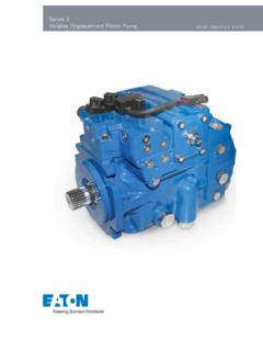
Transcription of Variable Axial Piston Pump A10V(S)O - D
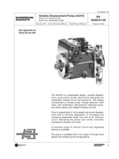
1 Industrial HydraulicsElectric Drives and ControlsLinear Motion and Assembly Technologies PneumaticsService AutomationMobile Hydraulics open circuitVariable Axial Piston Pump A10V(S)ORA 92 701 1/36 Replaces: 18 .. 140 Series 31 Nominal pressure 4000 psi (280 bar) Peak pressure 5100 psi (350 bar)Features Axial Piston pump A10VO, Variable , in swashplate design for hydrostatic transmissions in open loop circuit Flow is proportional to drive speed and displacement. By adjusting the swashplate angle it is possible to infinitely vary the flow Mounting flange acc.
2 To SAE J744 Flanged ports acc. to SAE J518 2 case drain ports Good suction characteristics Permissible working pressure 4000 psi (280 bar) Low noise level Long service life Axial and radial loading of drive shaft possible High power-weight ratio Wide range of controls Short response times Through drive option for multi-circuit systemContentsOrdering code standard range 2 Technical data 4 Noise Level 8 Drive power and flow 10DG - two point, direct control 12DR - Pressure control 14 DRG - Pressure control, remote 16 DFR / DFR1 - Pressure flow control 18 DFLR - Pressure / flow / power control 20 Unit dimensions, Size 18 22 Unit dimensions.
3 Size 28 23 Unit dimensions, Size 45 24 Unit dimensions, Size 71 25 Unit dimensions, Size 100 26 Unit dimensions, Size 140 27 Through drives 28 Overview of through drive mounting options 29 Unit dimensions combination pumps 29 Dimensions of through drives 30 Installation notes 34 Safety information 352/36 Bosch Rexroth AG | Mobile Hydraulics A10VO | RA 92 701 code standard range = available = in preparation = not available = preferred programVersion 18, 28 - H Axial Piston unit 18 design Variable - A10V - AA10VS Mode of operationPump open circuit O Size 18 28 45 71 100 140 Displacement Vg max in3/rev cm3/rev 18 28 45 71 100 140 Control devices 18 28 45 71 100 140 Two point.
4 Direct control DG DGPressure control DR DR DR G DRG remote controlPressure and flow control DFR DFR DFR 1 DFR1 orifice in X-channel closedPressure, flow and torque control - DFLRE lectro-hydr. pressure control, see RA 92707 EDPressure and flow control with electrically adjustable EF differential pressure see RE 92709 (in preparation) Series 31 Direction of rotation Viewed on drive shaft clockwise R counter clockwise L SealsNBR nitril-caoutchouc, shaft seal FKM PFKM fluoro-caoutchouc V Shaft end acc.
5 To SAE J744 18 28 45 71 100 140 Splined, reduced dia. (not for through drive) [in] 5/8 - 7/8 - 1 1/4 - USplined, regular dia. (with undercut) [in] 3/4 7/8 1 1 1/4 1 1/2 1 3/4 SSplined (with runout, higher input torque) [in] - 7/8 1 1 1/4 RSplined (with runout, reduced dia.) [in] 7/8 1 1/4 WParallel with key KTrapered with woodruff key - - - - CRA 92 701 | A10VO Mobile Hydraulics | Bosch Rexroth AG 3/36 A10V(S) O / 31 VersionAxial Piston unitMode of operationSizeControl devicesSeriesDirection of rotationSealsShaft endMounting flange acc.
6 To SAE J744 18 28 45 71 100 1402-hole - C4-hole D Port for service lines 18 28 45 71 100 140 Pressure port B SAE flange rear, - - - - - 91 Suction port S fixing thread UNCP ressure port B SAE flange on opposite side - - - - - 92 Suction port S fixing thread UNCP ressure port B SAE flange rear, - - 61 Suction port S fixing thread UNCP ressure port B SAE flange on opposite side - 62 Suction port S fixing thread UNC Through drive 18 28 45 71 100 140 Without through drive N00 With through drive (port plate 62 org2) Mounting flange1) Shaft/coupling2) Sealing82-2 (A) 16-4 (A) Axial K0182-2 (A) 19-4 (A-B) Axial K52101-2 (B) 22-4 (B) Axial K68101-2 (B) 25-4 (B-B)
7 Axial K04127-2 (C) 32-4 (C) Axial K07127-2 (C) 38-4 (C-C) Axial K24152-4 (D) 44-4 (D) Axial K171) Flange acc. to SAE J7442) Coupling for splined shaft acc. to SAE J744 OCT83 For mounting options on through drive see page plate 91 and 61 without through drive only4/36 Bosch Rexroth AG | Mobile Hydraulics A10VO | RA 92 701 -4 32 68 104 140 176 212 F-40 -20 0 20 40 60 80 100 C-40 -25 10 0 10 30 C50 70 90 115 -40 -13 14 32 50 86 F122 158 194 240 1600740010004600600300040020002001000100 5006030040200201001060mm2/sSUS5428074001 600170368016425 SUSmm2/stmax = 240 F (115 C)tmin = -40 F (-40 C)
8 VG 22VG 32VG 46VG 68VG 100 Notes on the selection of hydraulic fluidIn order to select the correct fluid, it is necessary to know the operating temperature in the tank (open circuit) in relation to the ambient hydraulic fluid should be selected so that within the ope-rating temperature range, the viscosity is within the optimum range ( opt.); see shaded section of the selection diagram. We recommend that the higher viscosity grade is selected in each : at an ambient temperature of X F ( C) the opera-ting temperature in the tank is 140 F (60 C).
9 In the optimum viscosity range opt (shaded area), this corresponds to viscosity grades VG 46 or VG 68, VG 68 should be : The leakage oil temperature is influenced by pres-sure and speed and is typically higher than the tank tempera-ture. However max. temperature at any point in the system may not exceed 239 F (115 C).At high temperatures please use FKM the above mentioned conditions cannot be kept due to extre-me operating parameters or high ambient temperatures, please consult of fluidThe finer the filtration, the better the achieved cleanliness of the fluid and the longer the life of the Axial Piston ensure a reliable functioning of the Axial Piston unit, a mini-mum cleanliness of 20/18/15 acc.
10 To ISO 44061) is very high fluid temperatures (195 F (90 oC) up to max. 239 F (115 C)) the minimum cleanliness has to be at least 19/17/14 acc. to ISO 44061). If the above cleanliness classes cannot be met please consult ) draft issue 1999 Technical dataFluidPrior to project design, please see our data sheets RA 90220 (mineral oil ) and RA 90221 (ecologically acceptable fluids) for detailed information on fluids and application conditions. When using ecologically acceptable fluids attention must be paid to possible limitations of the technical data.