Transcription of Variable Capacity Compressors, a new dimension …
1 1 Variable Capacity Compressors, a new dimension forrefrigeration engineers to exploreBy: Marcos G. Schwarz, VCC Group LeaderCorporate Research & Development, EMBRACO SAAbstract:This paper presents the basic aspects in refrigeration system design using Variable CapacityCompressors. It is a practical guide for engineers that focuses on energy savings and noise reduction andillustrates an optimized design in only a few improvement areas for the sealed system as it relates to the compressor are discussed and trendsfor Variable Capacity Compressors performance are to a 40% reduction in overall energy consumption and a 5 dB(A) average noise level reduction weremeasured applying Variable Capacity Compressors as compared to conventional fixed :Refrigeration systems are basically composed of one thermal insulated cabinet, designed to store andpreserve food, that is equipped with a mechanism that takes thermal energy out from this ambient andkeeps the low temperature inside compartments within defined limits.
2 It compensates the heat leakagethrough the insulation and the added energy by atmosphere replacement during door openings or storageof hot heat pumping mechanism for domestic refrigerators and freezers is called the Sealed System andconsists essentially of a compressor , evaporator, condenser, a device that controls the gas flow, and thegas load. The correct design of each element depends of the type of system and specific requiredperformance, and becomes more complex when sophisticated elements are applied like fan cooled heatexchangers, Variable gas flow restrictions, Variable Capacity compressors, heaters, air flow control complexity increases when multi-compartment systems are designed and the sophisticated devicesare back to the basics for refrigeration systems design, there are some rules that help designers makechoices for the basic elements when Variable Capacity Compressors are used, as well as to understandwhich elements are independent from this cooling Capacity modulation.
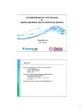
3 From these understandings it ispossible to make some valid conclusions about trends for Variable Capacity Compressors performance,which orient future targetsWhen a new appliance is designed, it becomes necessary to define the optimization functions. Thismeans identifying performance targets to be accomplished with minimum additional performance targets could be a specific energy level, noise level, freezing Capacity , cabinettemperature profile, internal volume or even some other specific target or combination of not always easy to define, it is essential to define this Optimization target before a new designis SavingsThe most important gain achieved by using Variable Capacity Compressors is reduction of energyconsumption, which is achievable in a number of different ways, as shown in figure 1 Energy Saving AlternativesIt is clear that thermal insulation, the intrinsic compressor COP (Coefficient of Performance whichexpresses the compressor s energy efficiency)
4 , and the thermodynamic behavior of the sealed system,are the basic areas with a fundamental effect on the appliance energy consumption, and can be workedindependently to obtain technology imposes some limitations. For example, there is a compromise between Thermalinsulation thickness and its performance, which affects appliance size, internal volume and MINIMUM STOP PERIODS FAVORABLE PRESSURESENERGY SAVINGALTERNATIVESSYSTEM TECHNOLOGYIMPROVEMENTS BETTER INSULATION HEAT EXCHANGER OPTIMIZATION AIR FLOW OPTIMIZATIONE nergy Saving Alternatives Variable CAPACITYCOMPRESSOR3 compressor EfficiencyIn case of compressor efficiency (COP), existing technology is also reaching limits for mechanical andelectrical loss reduction, as described in the fractional horsepower motors used in fixed speed hermetic compressor today avereached around 85 to 88% of efficiency. Mechanism losses are minimized by using low viscosity oils(ISO7) in combination with precise components and tied dimensional tolerances, as well as, specifictechniques to improve gas flow and thermal behavior.
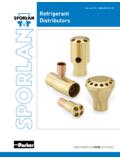
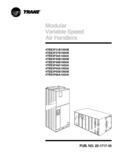
5 The result is compressors with a COP around 6 Btu/Wh (1,76 W/W) at Ashrae ReductionThe appliance s noise sources are the fans, mechanical switches, gas flow and the technologies have being improved in order to obtain lower acoustic noise emission, in alltechnical areas. These include shell design, internal transmission methods, cavity and componentresonance, damping and noise sources. Even with technology evolution, the basic behavior alwaysobserved is the noise level dependence to compressor speed and cooling Capacity , as showed in fig. 2 NoiseThe Variable Capacity compressor represents an excellent opportunity for a direct overall noisereduction in appliances, because it offers the possibility to operate most of time at speeds lower than3000 or 3600 (rpm)3032343638404244dB(A)Reciprocating CompressorR600a, 11cc displacementOverall Noise Level4 Capacity Modulation EffectIn order to achieve the required pull down time, fixed speed compressors select the cooling capacitybased on the maximum demand, at high ambient temperature, as illustrated in fig consequence is that compressor delivers high cooling Capacity , selected to overcome the worstcondition, and it needs to be cycled on and off, when normal conditions is achieved.
6 The results are ontimes typically from 30 to 60%, and consequent low COP during the running period, because of thehigh pressure drop between discharge and 3 Fixed Speed Design RulesBy using Variable Capacity Compressors, the cooling Capacity can be adjusted according the appliancedemand. Most of the time this Capacity is much lower than the maximum cooling Capacity thecompressor can deliver, and the result is normal operation at low speed. The direct effect of compressorspeed decrease is reduction of pressure drop between suction and discharge (lower mass flow), whichcauses the compressor to run more efficiently, compensating the longer periods it remains in on state ,and resulting in important energy a thermodynamics perspective, the limitations for better performance focus on heat exchangerefficiency, that depends on its size and thermal coupling to environment, and depends also on pressuredrop between discharge and suction.
7 These are factors that affect the heat exchanger and use of Variable Capacity Compressors plays an important role in this aspect. This relates to the factthat there is the possibility to easily adjust the cooling Capacity (mass flow) to the actual demand, createlonger cycles, virtually close to the ideal continuous operation , and minimize compressor start uplosses and heat reflow losses. This promotes minimum pressure drops between discharge and suctionsides, increasing substantially the real COP at the Design RulesSystem LoadFirst Time ON Heavy LoadingNormal UseNoDoor OpeningWinterSummerAmbient TempOperates Most of timeDesignedforthisSituation5 Possible Appliance Features using Capacity ModulationFrom a technical perspective, the Variable Capacity technology makes it easier to offer additionalfeatures which are preffered by the end user above and beyond energy savings and noise include quick freezing and deep freezing.
8 Inorder to achieve these features, compressors withconventional fixed speed technology, must be oversized. This oversizing increases the cost and noiselevels, and reduces energy system design for Variable Capacity CompressorFollowing picture summarizes the interdependence of the components (FIG 4) and the basic routine forrefrigeration systems design (FIG 5).FIG 4 Interdependence of the componentsFIG 5 Design Routine for Variable Capacity CompressorINTERDEPENDENCE BETWEENSYSTEM COMPONENTSCONDENSINGPRESSUREREFRIGERANTC HARGEEVAPORATINGPRESSUREAMBIENTTEMPERATU RECOMPRESSORCAPACITYRESTRICTION OF THECAPILLARY TUBEHEAT EXCHANGER SELECTIONCAPILLARY SELECTIONPROTOTYPEGAS CHARGE DETERMINATIONPERFORMANCE TESTSW orkableSystemSystemNEWSYSTEMWORKING CONDITIONSDEFINITIONT(c), T(e)THERMAL LOAD DEFINITIONQ(ss), Q(max)SELECTION OF COMPRESSORm(ss), m(max)EXISTINGSYSTEMO ptimizationLoopCONTROL STRATEGYDEFINITION6 Thermal load DeterminationThe Thermal Load must be determined when a new system is to be designed, as well as when anyexisting system is converted and optimized for VCC application.
9 This thermal load definition dependson several factors as illustrated in Fig 6 Thermal loadWorking conditionsCondensing and Evaporating temperatures, T(c) and T (e) can be defined based on temperature, T(c), corresponding to compressor discharge pressure, should be as low aspossible, minimizing compressor stress, and reducing energy temperature, T (e), corresponding to compressor suction pressure, should be as close aspossible to internal cabinet temperature, in order to maximize the overall sizingThe compressor is selected based on the minimum and maximum required cooling Capacity . ForVariable Capacity Compressors, the Cooling Capacity is no longer the correct way to identify aspecific model. The compressor displacement (cubic centimeters) now becomes the convenient way toidentify a model. Naturally, this is in correlation with the refrigerant used (R600a or R134a) andavailable speed State(Minimum cooling Capacity )Q(ss)Transient(Maximum Cooling Capacity )Q(max) Internal volome External Volume Type of insulation Climatic class ( 32C,25C ) Type of SystemQ(ss) = f Amount of mass tofreeze Time for temperature reduction Climatic class( 43C, 38C )Q(max) = f7 Maximum required cooling Capacity comes from thermal load required in the worst situation.
10 This Q(max) is the Capacity needed to accomplish appliance performance at critical situations like pull down athigh ambient temperature, or quick freezing, or deep freezing, whatever demands more to compressor cooling Capacity curves, at maximum speed, the lowest available compressordisplacement, D (a) for this application is identified. It does not mean the compressor is alreadyselected, it only mean the smallest model for this application was the minimum required cooling Capacity must be defined. This comes from thermal load at steadystate condition, Q (ss). As a first design step, the compressor is selected in order to accomplish steadystate conditions, for energy consumption to compressor cooling Capacity curves, now at minimum speed, the compressor displacementfor steady state condition, D (ss) is identified. It is probable that D (a) is different from D (ss).It is important to comment that keeping compressor running 100% of the time and adjusting speed tocompensate the required thermal load at any time, in practice, is not the optimal point for energyconsumption, because compressors do not keep COP constant when cooling Capacity is COP reduces as the speed reduces, which is due to fixed electrical losses.