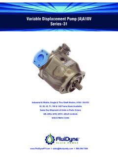
Transcription of Variable Displacement Pump (A)A10V Series-31
1 Variable Displacement Pump (A)A10V Series-31 Industrial & Mobile, Single & Thru Shaft Models, A10V / AA10V18, 28, 45, 71, 100 & 140 Frame Sizes AvailableSame Day Shipment of Units or Parts OrdersDR, DRG, DFR, DFR1, DFLR ControlsSAE & Metric I I 586-296-72002 Variable Displacement Pump (A)A10V, series Displacement Pump (A)A10V, series 31 ..4 Features ..4 Technical Data ..5 Ordering Code ..6 Fluid Operational Conditions ..8 Noise Level ..9 DR Pressure Control Data, Dimensions ..10 DRG Pressure Control Data / Remote Control / Dimensions ..12 DFR/DFR1 Pressure / Flow Control ..13 DFLR Pressure / Flow / Power Control / Dimensions ..15 Mounting Dimensions, Size 18, series 31 ..17 Service Ports on Side; Non Through Drive, Models 62N00 and 12N00 ..17 Mounting Dimensions, Size 28, series 31 ..18 Service Ports at Side and Rear; Non Through Drive ..18 (A)A10V28 Shaft, Metric Mount, and Port Dimensions.
2 19 Mounting Dimensions, Size 45, series 31 ..20 Service Ports at Side and Rear; Non Through Drive ..20 (A)A10V45 Shaft, Metric Mount, and Port Dimensions ..21 Mounting Dimensions, Size 71, series 31 ..22 Service Ports on Side and Rear; Non Through Drive ..22 (A)A10V71 Shaft, Metric Mount, and Port Dimensions ..233 Variable Displacement Pump (A)A10V, series Displacement Pump (A)A10V, series 31 ..4 Features ..4 Technical Data ..5 Ordering Code ..6 Fluid Operational Conditions ..8 Noise Level ..9 DR Pressure Control Data, Dimensions ..10 DRG Pressure Control Data / Remote Control / Dimensions ..12 DFR/DFR1 Pressure / Flow Control ..13 DFLR Pressure / Flow / Power Control / Dimensions ..15 Mounting Dimensions, Size 18, series 31 ..17 Service Ports on Side; Non Through Drive, Models 62N00 and 12N00 ..17 Mounting Dimensions, Size 28, series 31 ..18 Service Ports at Side and Rear; Non Through Drive.
3 18 (A)A10V28 Shaft, Metric Mount, and Port Dimensions ..19 Mounting Dimensions, Size 45, series 31 ..20 Service Ports at Side and Rear; Non Through Drive ..20 (A)A10V45 Shaft, Metric Mount, and Port Dimensions ..21 Mounting Dimensions, Size 71, series 31 ..22 Service Ports on Side and Rear; Non Through Drive ..22 (A)A10V71 Shaft, Metric Mount, and Port Dimensions ..23 Mounting Dimensions, Size 100, series 31 ..24 Service Ports on Side Non Through Drive ..24 (A)A10V100 Shaft, Metric Mount, and Port Dimensions ..25 Mounting Dimensions, Size 140, series 31 ..26 Service Ports on Side; Non Through Drive, Models 62N00 and 12N00 ..26 Through Drive ..27 Overview of Through Drive Mounting Options / Dimensions ..27 Shaft Torque Data ..27 Pump Installation Notes ..314 Variable Displacement Pump (A)A10V, series Axial piston pump A10V in swashplate design is used for hydrostatic transmissions in open loop circuits.
4 Flow is proportional to drive speed and Displacement . By adjusting the position of the swashplate it is possible to smoothly vary the flow. Flange connections to SAE-UNC or Isometric 2 case drain ports High permissible speeds Good suction characteristics Low noise level High power/weight ratio Long service life Quick response time Axial and radial loading of drive shaft possible Wide range of controls Through drive option for multi-circuit systemSwashplateCylinderblockVariablepis tonPistonValveplateDFRcontrol valveEnd coverHousingShaftReturning pistonVariable Displacement Pump (A)A10V, series 315 Variable Displacement Pump (A)A10V, series Data 1. Input operating pressure range Absolute pressure at port S (A) Pabs (12 psi) Pabs (435 psi) 2. Output operating pressure range Pressure at port B Nominal pressure (4000 psi) Peak pressure (5100 psi) Pressure data to DIN243123.
5 Case drain pressure Maximum pressure of leakage fluid ( at ports L, L1 ). Maximum 7 psi ( bar ) higher than input pressure at port S, but not higher than 30 psi ( 2 bar ) absolute. 4. Direction of flow : ( S to B )5. Table of values (theoretical values, without considering mh and v ; values rounded) Size cm3/rev18284571100140 DisplacementVg maxcm3/rev (in3/rev)18 ( )28 ( )45 ( )71 ( )100 ( )140 ( )Max. Speed No maxrpm330030002600220020001800 Max. FlowOo maxL / min (gpm) ( )84 (22)117 (31)156 (41)200 (53)252 (67)Max. PowerPo maxkW (HP)28 ( )39 (51)55 (72)73 (96)93 (124)118 (156)Max. Torque @Vg max, No maxTmaxNm (ft - lb) 80 (58)125 (91)200 (146)316 (230)w445 (324)623 (453)Weight (without fluid) Kg (lbs)12 (27)15 (33)21 (46)33 (73)45 (99)60 (132) Notes: Values shown are valid for an absolute pressure of 1 bar at suction port. If the flow is reduced or if the inlet pressure is increased the speed may be increased.
6 6. Determination of size Flowqv =[gpm]qv =[L/min]TorqueT =[lb-ft]T =[Nm]PowerP =[HP]P =[kW]Vg n v1000 Vg p20 mh qv pVg= Displacement per revolution in in3 (cm3) p=Di erential pressure in psi (bar)n=Speed in rpm (min 1) v=Volumetric e ciency mh=Mechanical-hydraulic e ciency t=Total e ciency 600 tVg n v23124 mh qv p1714 t Vg p((())) Variable Displacement Pump (A)A10V, series 316 Variable Displacement Pump (A)A10V, series Piston Unit (A)A10V(S)O71DR/ 31R - PSC62N00 Swash plate Variable pumpA10 VSwash plate Variable pump for industrialA10 VSMode of Operation Pump, open circuitOSize Displacement Vgmax cm3//rev (in3//rev)18( )28( )45( )71( )100( )140( )Control Devices Pressure control Pressure remote controll l l l l lDRDRGP ressure and flow control Pressure & flow (w/ X port blocked)l l l l l lDFRDFR1 Pressure,Flow & Power controll l l l l lDFLRS eriesSeries31 Direction of Rotation Viewed from shaft endclockwiseRcounter-clockwiseLSealsBuna -N (NBR per DIN IS0 1629).
7 PFPM (flurocarbon)VShaft End 18284571100140 SAE-splined shaftl l l l l lSSAE-splined shaft, reinforced (higher thru drive torque)l l l l--RSAE splined shaft, smaller size (not for pumps with thru drive) l-l l l-USAE- splined shaft, reinforced (U-type shaft)l l l l l-WSAE- keyed shaftl l l l l lKParallel with key DIN 6885l l l l l lPOrdering Code Variable Displacement Pump (A)A10V, series 317 Variable Displacement Pump (A)A10V, series (A)A10V(S)O71DR/ 31R - PSC62N00 Through drives 18 28 45 71 100 140 Without through drive (Non-Thru Drive)l l l l l lN00 With through drive to accept an axial piston pump or a gear pumpMounting flange SAEJ744 hub sealing to mount82-2 (A) 3/4 keyed (A-B) axial A10V18 (K)Ol l l l lK401)101-2 (B) 7/8 keyed (B) axial A10V28 (K)-l l l l lK031)101-2 (B-B) 1 keyed (B-B) axial A10V45 (K) - -l l l lK051)127-2 (C) 1-1/4 keyed (C) axial A10V71 (K)- - -l l lK081)127-2 (C) 1-1/2 keyed (C) radial A10V100 (K) - - - -l lK381)152-4 (D) 1-3/4 keyed (D) axial A10V140 (K)- - - - -lK211)82-2 (A) 5/8 9T (A) axial A10V18(U)l l l l l lK0182-2 (A) 3/4 11T (A-B) axial A10V18(S,R), 10(S)l l l l l lK52101-2 (B) 7/8 13T (B) axial A10V28(S,R), 45(U,W)
8 -l l l l lK68/K02101-2 (B) 1 15T (B-B) axial A10V45(S,R), 60(U,W)- -l l l lK04127-2 (C) 1-1/4 14T (C) axial A10V71(S,R), 100 (U,W)- - -l l lK07/K15127-2 (C) 1-1/2 17T (C-C) axial A10V100(S,R), 85(S)- - - -l lK24152-4 (D) 1-3/4 13T (D) axial A10V140(S,R)- - - - -lK17 Service Ports(Pressure port B and Suction port S)18284571100140 Rear ports, UNC mounting screwsl l l l-61 Ports 61, 11, 91 & 41 non-through drive onlyOpposite side ports, UNC mounting screwsl l l l l l62 Rear ports, metric mounting screwsl l l--11 Opposite side ports, metric mounting screwsl l l l l12 Rear ports, UNC mounting screws--l--91 Opposite side ports, UNC mounting screws--l--92 Rear ports, metric mounting screwsl-41 Opposite side ports, metric mounting screws--l--42 Mounting Flange 18 28 45 71 100 140 SAE 2 holel l l l l-CISO 2 hole-l l l l-ASAE 4 hole-----lDl = availableO = in preparation - = not available See Thru Drives section for other optionsVariable Displacement Pump (A)A10V, series 311) Permitted with reduced thru drive torque8 Variable Displacement Pump (A)A10V, series 1.
9 Fluid: AW68 (Q / TCNK 12-2001) 2. Operating viscosity range V opt = 16 mm2 / s ~ 36 mm2 / s (80-170 sus) For optimum efficiency and service life we recommend that the operating viscosity (at operating temperature) be selected in the range: V opt = opt. operating viscosity 16 ~ 36 mm2 / s Referred to tank temperature (open loop circuit). Limits of viscosity range (The following values are valid for extreme operating conditions): V min = 10 mm2 / s (60 sus) For short periods (t 1 minute) at max. leakage oil temperature of 800C (176 0F) V max = 1000 mm2 / s For short periods upon cold start 3. Temperature range T min = -200C (-130F) : T max = +800C (+1760F)4. Filtration In order to ensure reliable operation of the axial piston unit the operating fluid must be maintained to a cleanliness class of at least 16 / 19 to IS04406. This may be achieved with filter elements with a cleanliness code of 10 Notes The pump housing must be filled with fluid during commissioning and remain full when operating.
10 The concentricity between engine transmission shaft and pump shaft must be less than ( in). Variable Displacement Pump (A)A10V, series 31 9 Variable Displacement Pump (A)A10V, series Displacement Pump (A)A10V, series 31 *Sound data representative of piston pumps of this Level Characteristics for pump Measured in an sound chamberDistance from microphone to pump = ft (1m)Measuring error: + 2 dB(A)Fluid: Hydraulic oil to ISO VG 46 DIN 51519, t=122 F(50 C)10 Variable Displacement Pump (A)A10V, series Pressure Control The pressure control serves to maintain a constant pressure in the hydraulic system within the control range of the pump. The pump therefore supplies only the amount of hydraulic fluid required by the actuators. Pressure may be smoothly set at the pilot valve. Ports BPressure portSSuction portL, L1 Case drain ports (L1 sealed)Control Data Hysteresis and repetitive accuracy.