Transcription of Variable Flow Pumps – Control Strategies
1 Variable Flow Pumps Control Strategies BBT Conference Feb 4/5, 2015. Presented by Steve Thompson VP - Residential Product Management Taco Inc. Mobile (401) 441-2934. E Mail: Variable Flow Pumps Control Strategies Agenda: Introduction General Descriptors VFD or not VFD That is the Question (VFD Assessment Tool). System & Pump Curves Selfsensing Pumps Applications Balancing VFD Pumping Systems delta T. Warning!!! Efficiency To trim or not to trim ECM Permanent Magnet Technology Affinity Laws Commissioning Tips DOE / ASHRAE / ACEEE. 1. General Descriptors T Differential Temperature Net temperature differential between two points (typically supply and return). 20 Deg F Normal differential temperature design for high mass, medium temperature systems 10 to 15 Deg F for radiant 10 to 12 Deg F for chilled water primaries Setpoint Temperature Temperature sensed at single location If sensor built into the pump, the pump must be installed at sensing location Make-up air coil a good example P Differential Pressure Pressure measured or sensed across two points Typical closed loop system pup inlet pressure is relatively constant PC Differential Pressure Constant (flat pump curve).
2 PV Proportional Pressure (inclining pump curve). Self Sensing Pump (Circ) adjusts speed without any physical sensors Reacts to changes in impeller loading as a result of system flow change Primary Circuit Dedicated to moving fluid to/from heating or cooling source Secondary Circuit Supplies fluid to building conditioned space Circulator vs Pump Pumps boost pressure (Well Pumps , Pressure Booster Pumps , Boiler Feed Pumps Circulators invoke fluid movement by overcoming friction loss (could be any Hp). Residential vs Commercial What's a Variable Flow System Application And Why Does This Matter? An HVAC system is like our body Brain = BMS (BAS) system Heart = pump Stomach = boiler or chiller Arteries = piping system Working out - system under load Body - heart rate up, increased blood pressure, consumes more energy Building more BTU's (flow), more head Sleeping - system under low load or setback Body heart rate and blood pressure down, consumes less energy Building less BTU's, lower head At least that's the way it is supposed to work!)
3 What if our heart and blood pressure didn't change? Conclusion all HVAC APPS are Variable flow! 2. Start VFD Assessment New Systems Need to vary No duty Consider fixed speed Pumps , On-Off continuously Control , Multiple sizes, etc. Yes VFD potentially useful No Check overall benefits Mostly including non-energy items friction? : reduced maintenance cost Yes VFD potentially useful Calculate total annual operating cost with alternative system solutions Does the pump No run most of the No Use fixed time? Is VFD suitable? speed Viridian Yes Yes VFD almost certainly beneficial Use VFD. Start VFD Assessment Retrofit Systems No Confirm existing fixed No Is duty Consider modification or speed pump is Variable replacement of equipment correctly sized Yes Yes Retain existing VFD potentially useful installation if efficient Check overall benefits No including non-energy items Mostly : reduced maintenance cost friction? Yes Calculate total annual operating cost with alternative VFD potentially useful system solutions Yes Is VFD No Does the pump No suitable?
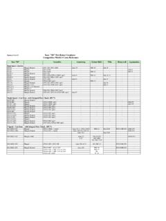
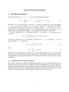
4 Run most of the time? Are existing pump and No Yes motor suitable for proposed VFD. VFD almost certainly beneficial Yes VFD. 3. System Curves 3-Way Control Valve 60 GPM each fan coil Design Operating Point 300 Gallons Per Minute 53 Feet of Head 150 ton system @ 12deg delta T. System Curves System Capacity Design Operating Point Head (H) in (Q) in Feet GPM. 0. 7. 25. 53. 90. 136. 4. System Curves Pump Curves Pump Curve 70. KS Model 4009. Test Data at 1760 RPM 60. " Diameter 50. Head (H) in Feet Capacity Head Efficienc BHP. (GPM) (Ft) y (%) (HP) 40. 30. 20. 10. 0. 0 100 200 300 400 500. Flow (Q) in GPM. 5. System Curves 3-Way Control Valve Pump Curves This image cannot currently be display ed. KS Model 4009. With an impeller Test Data at 1760 RPM. Pump System Capacity Efficiency BHP Head Head (Ft). (GPM) (%) (HP) (Ft). 0. 6. SelfSensing Pumps Variable Loads (Zones Closing). 3-Way Valve SelfSensing Pumps Valves Closed Valves Open Minimum Flow Maximum Flow 100.
5 90. 80. 70. Head (Ft.). 60. 50. 40. 30. 20. 10. 0. 0 50 100 150 200 250 300 350 400 450. Flow (GPM). 7. SelfSensing Pumps Valves Closed Valves Open 100. Minimum Flow Maximum Flow 90. 80. 70. 60. Head (Ft.). 50. 40 60 Hz 30. 50 Hz 40 Hz 20. 30 Hz 10. 20 Hz 0. 0 50 100 150 200 250 300 350 400 450. Flow (GPM). SelfSensing Pumps Valves Closed Valves Open 100. Minimum Flow Maximum Flow 90. 80. 70. 60. Head (Ft.). 50. 60 Hz Control Curve 40. 30. 20. 20 Hz 10. 0. 0 50 100 150 200 250 300 350 400 450. Flow (GPM). 8. Integrated VFD with Sensorless Control Constant Pressure Mode Proportional Pressure Mode True System Curve Mode Applications Example: Chilled water primary / secondary system 9. Constant Flow Mode Self-sensing CONSTANT flow is self-balancing and automatically adjusts flow to maintain user-defined flow set point. Used on constant flow chiller / boiler Pumps Benefits: Balancing through reduced speed not false head Reduced speed increases equipment life Balancing done internally and automatically Auto adjust over the life and fouling of the system Using full trim impellers Allows for design reality differences Variable Flow Mode Self-sensing Variable flow adapts to system pressure variations and automatically follows the system performance curve to meet demand.
6 Used on secondary Variable speed Pumps Benefits: Lower install costs No error in setpoint Improved system efficiency and performance Reduced coordination and construction schedule 10. Variable flow Direct Return Piping System Constant flow (first in / first out). Balancing complexity - high TERMINAL UNITS. HYDRONIC VALVE Control . VALVE. MULTIPURPOSE. VALVE BALANCE. HIGH EFFICIENCY VALVE. AIR & DIRT SEPERATOR SUPPLY PIPE. SUCTION TACO VERTICAL. DIFFUSER INLINE PUMP. RETURN PIPE. EXPANSION BOILER. TANK. Variable flow Reverse Return Piping System Constant flow (first in / last out). Balancing complexity low TERMINAL UNITS. Self Balancing HYDRONIC VALVE Control . VALVE. MULTIPURPOSE. VALVE BALANCE. HIGH EFFICIENCY VALVE. AIR & DIRT SEPERATOR SUPPLY PIPE. RETURN PIPE. SUCTION TACO VERTICAL. DIFFUSER INLINE PUMP. EXPANSION BOILER. TANK. 11. Variable flow Primary Secondary Systems Constant flow (pumped secondary). Balancing complexity depends TERMINAL UNITS.
7 HYDRONIC VALVE Control . VALVE. MULTIPURPOSE. VALVE BALANCE. HIGH EFFICIENCY SUPPLY PIPE VALVE. AIR & DIRT SEPERATOR. CROSSOVER. BRIDGE. SUCTION TACO VERTICAL. DIFFUSER INLINE PUMP. RETURN PIPE. EXPANSION BOILER. TANK. Variable flow . Constant flow Injection Pumping System Balancing complexity TERMINAL UNITS. Crossover bridges balance Which circs Variable flow? CIRCULATING. PUMP. INJECTION. PUMP. BALANCE. MULTIPURPOSE SUPPLY PIPE VALVE. HIGH EFFICIENCY VALVE. AIR & DIRT SEPERATOR RETURN PIPE. SUCTION TACO VERTICAL. DIFFUSER INLINE PUMP. EXPANSION BOILER. TANK. 12. Variable flow LoadMatch TM. Single Pipe Pumping System Constant flow . Balancing complexity none req'd TERMINAL UNITS. Circs Variable flow? LOADMATCH. CIRCULATOR. TWIN. TEE. MULTIPURPOSE. HIGH EFFICIENCY VALVE. AIR & DIRT SEPERATOR. PRIMARY LOOP. SUCTION TACO VERTICAL. DIFFUSER INLINE PUMP. EXPANSION BOILER. TANK. Balancing VFD Systems (ASHRAE). The main goal of the secondary chilled water system is to distribute the correct amount of water to satisfy the load.
8 It must first accurately monitor the system for changes in load dynamics. Secondly, it must respond to these load changes with the correct amount of flow Run VFD's at constant speed balance then set Pumps to AUTO. 13. SelfSensing Pumps vs. Sensors Sensors are frequently placed in the wrong location in the system; this incorrect sensor placement results in system inefficiency. In a typical system, trial and error must be used ( physically moving the sensor) until the optimum location is determined. Another strategy is to use multiple sensors to increase the odds of correct placement. These Strategies can become costly. Even if correct placement is achieved, correct setpoint is rarely used. Determining the Set Point for the Differential Pressure Sensor The sensor must keep enough pressure differential across the supply and return to push . the design capacity flow through the coil and Control valve. Setpoint=Sum of coil pressure drop + Control valve pressure drop at design conditions (17').
9 14. Location of P Transmitters Effeciencies are dramatically affected TERMINAL. UNIT. DIFF. PRESSURE Control . VALVE. TRANSMITTER. BYPASS. W/VALVE. PRIMARY. PUMP 80' setpoint TERMINAL. UNIT. Control . VALVE. BYPASS. W/VALVE. PRIMARY DIFF. PRESSURE. PUMP TRANSMITTER. 17' setpoint Differential Temperature delta -T lends itself to even more cost effective Variable speed pumping. The issues associate with placement and of delta -P sensors is replaced with ease and simplicity of thermisters. As the delta -T falls below setpoint, the Pumps would slow down. As the delta -T rises above setpoint, the Pumps speed up. Remember that BTUH = GPM x T x 500. 15. Caution Boiler Temperature Sensor Location Consideration Be careful with sensor location for boiler plant Control Sensors right at plant discharge can cause boiler short cycling because of lack of thermal mass The short cycling can significantly hurt system efficiency. Newer lower mass high efficiency boilers are very sensitive to low flow rates in the system (VFDs) and need a thermal flywheel.
10 (Buffer tank). Variable Speeds and Mechanical Seals CAUTION! Minimum Speeds Effect Mechanical Seals Noise (remember the noise when you turn a pump off during the last few revolutions it's dry a dry running seal Seal face lubrication Rules of Thumb 4 Pole (1,750 RPM) min 15 Hz, preferably 20 Hz 6 Pole (1,150 RPM) min 25 Hz 16. Causes of Excess System Flow Poor / excessive balancing Poor Control valve selection (oversizing). Improper installation of Control sensors Set point too high on DP transmitters Oversized Pumps (with/without VFD's). P transducers in the wrong location is a common mistake (see next slide). Universal Problems The secondary system will try to distribute more chilled water than is needed. This is inefficient and used excess horsepower Higher flow causes low system temperature differentials, excess flow and change in flow direction in the crossover bridge The chiller plant must keep more chillers on-line than is required by the load.)