Transcription of VARIOUS TYPES OF SLABS - Memphis
1 VARIOUS TYPES OF SLABS . 1. CHOICE OF TYPE OF slab FLOOR. The choice of type of slab for a particular floor depends on many factors. Economy of construction is obviously an important consideration, but this is a qualitative argument until specific cases are discussed, and is a geographical variable. The design loads, required spans, serviceability requirements, and strength requirements are all important. For beamless SLABS , the choice between a flat slab and a flat plate is usually a matter of loading and span. Flat plate strength is often governed by shear strength at the columns, and for service live loads greater than perhaps 100 lb/ft2 ( kN/m2) and spans greater than about 20 to 24 ft (7. to 8 m) the flat slab is often the better choice. If architectural or other requirements rule out capitals or drop panels, the shear strength can be improved by using metal shear heads or some other form of shear reinforcement, but the costs may be high. Serviceability requirements must be considered, and deflections are sometimes difficult to control in reinforced concrete beamless SLABS .
2 Large live loads and small limits on permissible deflections may force the use of large column capitals. Negative-moment cracking around columns is sometimes a problem with flat plates, and again a column capital may be useful in its control. Deflections and shear stresses may also be controlled by adding beams instead of column capitals. If severe deflection limits are imposed, the two-way slab will be most suitable, as the introduction of even moderately stiff beams will reduce deflections more than the largest reasonable column capital is able to. Beams are also easily reinforced for shear forces. The choice between two-way and beamless SLABS for more normal situations is complex. In terms of economy of material, especially of steel, the two-way slab is often best because of the large effective depths of the beams. However, in terms of labor in building the floor, the flat plate is much cheaper because of the very simple formwork and less complex arrangement of steel. The flat slab is somewhat more expensive in labor than is the flat plate, but the forms for the column capitals are often available as prefabricated units, which can help limit costs.
3 The real cost parameter is the ratio of costs of labor relative to material. Few two-way SLABS are built in areas of high labor costs unless there are definite structural reasons, and many are built where steel is the most costly item. Hollow-tile SLABS are still built in some places, but only where the cost of both steel and cement is very high relative to labor. Local customs among builders, designers, and users should not be overlooked when selecting the slab type. There is a natural human tendency to want to repeat what one has previously done successfully, and resistance to change can affect costs. However, old habits should not be allowed to dominate sound engineering decisions. If a flat plate or flat slab is otherwise suitable for a particular structure, it will be found that there is the additional benefit of minimizing the story height. In areas of absolute height restrictions, this may enable one to have an additional floor for approximately each 10 floors, as compared with a two-way slab with the same clearstory heights.
4 The savings in height lead to other economies for a given number of floors, since mechanical features such as elevator shafts and 2. piping are shorter. There is less outside wall area, so wind loadings may be less severe and the building weighs less, which may bring cost reductions in foundations and other structural components. There are other cost savings when the ceiling finishes can be applied directly to the lower surfaces of the SLABS . Beamless SLABS will be at a disadvantage if they are used in structures that must resist large horizontal loads by frame action rather than by shear walls or other lateral bracing. The transfer of moments between columns and a slab sets up high local moments, shears, and twisting moments that may be hard to reinforce for. In this situation, the two-way slab is the more capable structure because of the relative ease with which its beams may be reinforced for these forces. In addition, it will provide greater lateral stiffness because of both the presence of the beams and the greater efficiency of the beam-column connections.
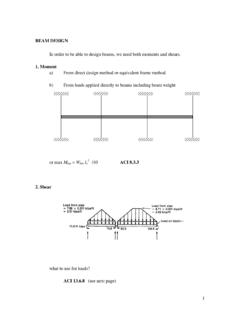
5 The possible choice of a precast one-way floor system, consisting of prestressed concrete members placed side-by-side and spanning between the beams, girders, or walls and generally covered by a cast-in-place concrete topping slab , should not be overlooked. 3. DESIGN OF ONE-WAY SLABS . The structural action of a one-way slab may be visualized in terms of the deformed shape of the loaded surface. Figure 1 shows a rectangular slab , simply supported along its two opposite long edges and free of any support along the two opposite short edges. If a uniformly distributed load is applied to the surface, the deflected shape will be as shown by the solid lines. Curvatures, and consequently bending moments, are the same in all strips s spanning in the short direction between supported edges, whereas there is no curvature, hence no bending moment, in the long strips l parallel to the supported edges. The surface is cylindrical. Figure1. Deflected Shape of Uniformly Loaded One-Way slab . Figure 2. Deflected Shape of Uniformly Loaded One-Way slab .
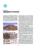
6 4. For purposes of analysis and design, a unit strip of such a slab cut out at right angles to the supporting beams, as in Figure 2, may be considered as a rectangular beam of unit width, with a depth h equal to the thickness of the slab and a span la equal to the distance between supported edges. This strip can then be analyzed by the methods that were used for rectangular beams, the bending moment being computed for the strip of unit width. The load per unit area on the slab becomes the load per unit length on the slab strip. Since all the load on the slab must be transmitted to the two supporting beams, it follows that all the reinforcement should be placed at right angles to these beams, with the exception of any bars that may be placed in the other direction to control shrinkage and temperature cracking. A one-way slab thus consists of a set of rectangular beams side by side. This simplified analysis, which assumes Poisson's ratio to be zero, is slightly conservative. Actually, flexural compression in the concrete in the direction of la will result in lateral expansion in the direction of lb unless the compressed concrete is restrained.
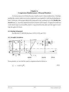
7 In a one-way slab , this lateral expansion is resisted by adjacent slab strips, which tend to expand also. The result is a slight strengthening and stiffening in the span direction, but this effect is small and can be disregarded. The ratio of steel in a slab can be determined by dividing the sectional area of one bar by the area of concrete between two successive bars, the latter area being the product of the depth to the center of the bars and the distance between them, center to center. The ratio of steel can also be determined by dividing the average area of steel per foot of width by the effective area of concrete in a 1 ft strip. The average area of steel per foot of width is equal to the area of one bar times the average number of bars in a 1 ft strip (12 divided by the spacing in inches), and the effective area of concrete in a 1 ft (or 12 in.) strip is equal to 12 times the effective depth d. 5. To illustrate the latter method of obtaining the steel ratio r, assume a 5 in. slab with an effective depth of 4 in.
8 , with No. 4 bars spaced 4 1/2 in, center to center. #4 bars 4". 4-1/2 ". As of one bar in slab =. area of concrete between two successive bars average area of steel per ft of width =. effective area of concrete in 1 ft of strip where average area of steel per ft of width = As of one bar times average number of bars in one foot. 12. average number of bars = = average steel area in 12 in strip = ( 2 ) = in 2. = = 12 4. or = = 4. The spacing of bars that is necessary to furnish a given area of steel per foot of width is obtained by dividing the number of bars required to furnish this area into 12. For example, to furnish an average area of in2/ft, with No. 4 bars, requires / 0. 20 = bars per foot; the bars must be spaced not more than 12 = in. center to center. The determination of slab steel areas for VARIOUS combinations of bars and spacing is facilitated by the following table. 6. Design moments and shears in one-way SLABS can be found either by elastic analysis or through the use of the same coefficients as used for beams (ACI ).
9 If the slab rests freely on its supports, the span length may be taken equal to the clear span plus the depth of the slab but need not exceed the distance between centers of supports, according to ACI Code In general, center-o-enter distances should be used in continuous slab analysis, but a reduction is allowed in negative moments to account for support width. For SLABS with clear spans not more than 10 ft that are built integrally with their supports, ACI. Code permits analysis as a continuous slab on knife-edge supports with spans equal to the clear spans and the width of the beams otherwise neglected. If moment and shear coefficients are used, computations should be based on clear spans. One-way SLABS are normally designed with tensile steel ratios well below the maximum permissible value to have tension failure. Typical steel ratios range from about to This is partially for reasons of economy, because the saving in steel associated with increasing 7. the effective depth more than compensates for the cost of the additional concrete , and partially because very thin SLABS with high steel ratios would be likely to permit large deflections.
10 Thus, flexural design may start with selecting a relatively low steel ratio, say about b, setting Mu =. Mn and solving for the required effective depth d, given that b = 12 in. for the unit strip. ACI Code specifies the minimum thickness in Table 1 for non-prestressed SLABS of normal weight concrete (wc = 145 pcf) using Grade 60 reinforcement, provided that the slab is not supporting or attached to construction that is likely to be damaged by large deflections. Lesser thicknesses may be used if calculation of deflections indicates no adverse effects. For concretes having unit weight wc, in the range from 90 to 120 pcf, the tabulated values should be multiplied by ( ), but not less than For reinforcement having a yield stress fy other than 60,000 psi, the tabulated values should be multiplied by ( + fy/100,000). slab deflections may be calculated, if required, by the same methods as for beams. Table 1. Minimum thickness h of nonprestressed one-way SLABS Simply supported l/20. One end continuous l/24.