Transcription of VE.Bus BMS - Victron Energy
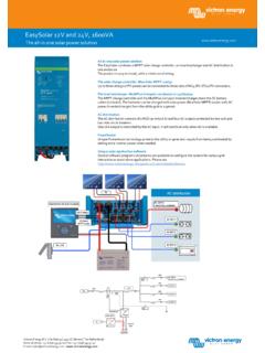
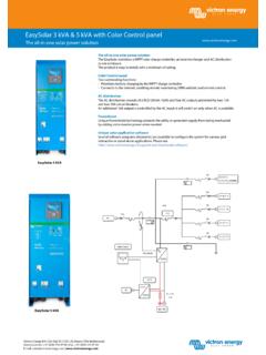
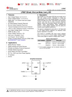
1 BMS Figure 1: Application example for a vehicle or boat. A Cyrix Li -ion Battery Combiner is used to connect to the starter battery and alternator. The UTP cable to the inverter/charger also provides the minus connection to the BMS. Protects each individual cell of a Victron lithium iron phosphate (LiFePO4 or LFP) battery Each individual cell of a LiFePO4 battery must be protected against over voltage, under voltage and over temperature. Victron LiFePO4 batteries have integrated Balancing, Temperature and Voltage control (acronym: BTV) and connect to the BMS with two M8 circular connector cord sets.
2 The BTVs of several batteries can be daisy chained. Up to five batteries can be paralleled and up to four batteries can be series connected (BTVs are simply daisy-chained) so that a 48V battery bank of up to 1500Ah can be assembled. Please see our LiFePO4 battery documentation for details. The BMS will: - shut down or disconnect loads in case of imminent cell under voltage, - reduce charge current in case of imminent cell overvoltage or over temperature ( products only, see below), and - shut down or disconnect battery chargers in case of imminent cell overvoltage or over temperature.
3 Protects 12V, 24V and 48V systems The operating voltage range of the BMS: 9 to 70V DC. Communicates with all products The BMS connects to a MultiPlus, Quattro or Phoenix inverter with a standard RJ45 UTP cable. Other products, without , can be controlled as shown below: Load Disconnect The Load Disconnect output is normally high and becomes free floating in case of imminent cell under voltage (default 3,1V/cell, adjustable on the battery between 2,85V and 3,15V per cell). Maximum current: 2A.
4 The Load Disconnect output can be used to control - the remote on/off of a load, and/or - the remote on/off of an electronic load switch (Battery Protect) Pre-alarm The pre-alarm output is normally free floating and becomes high in case of imminent cell under voltage (default 3,1V/cell, adjustable on the battery between 2,85V and 3,15V per cell). Maximum current: 1A (not short circuit protected). The minimum delay between pre-alarm and load disconnect is 30 seconds. Charge Disconnect The Charge Disconnect output is normally high and becomes free floating in case of imminent cell over voltage or over temperature.
5 Maximum current: 10mA. The Charge Disconnect output can be used to control - the remote on/off of a charger and/or - a Cyrix-Li-Charge relay and/or - a Cyrix-Li-ct Battery Combiner LED indicators - Enabled (blue): products are enabled. - Cell>4V or temperature (red): charge disconnect output low because of imminent cell over voltage or over temperature. - Cell>2,8V (blue): load disconnect output high. BMS Victron Energy | De Paal 35 | 1351 JG Almere | The Netherlands General phone: +31 (0)36 535 97 00 |E-mail: BMS Input voltage range 9 70V DC Current draw, normal operation 10 mA (excluding Load Disconnect current) Current draw, low cell voltage 2mA Load Disconnect output Normally high Source current limit: 2A Sink current: 0 A (output free floating) Charge Disconnect output Normally high Source current limit: 10mA Sink current.
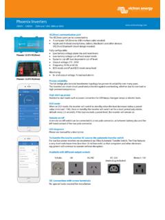
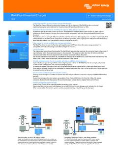
6 0 A (output free floating) Pre-alarm output Normally free floating High (Vbat) in case of alarm, max. 1A (not short circuit proof) GENERAL communication port Two RJ45 sockets to connect to all products Operating temperature -20 to +50 C 0 - 120 F Humidity Max. 95% (non-condensing) Protection grade IP20 ENCLOSURE Material and colour ABS, matt black Weight 0,1kg Dimensions (h x w x d) 105 x 78 x 32mm STANDARDS Standards: safety Emission Immunity Automotive EN 60950 EN 61000-6-3, EN 55014-1 EN 61000-6-2, EN 61000-6-1, EN 55014-2 Regulation UN/ECE-R10 Figure 2: Application example for a vehicle or boat, without inverter/charger.
7 Cyrix Combiners especially designed for use with the BMS: Cyrix-Li-ct (120A or 230A) Is a battery combiner with a Li-ion adapted engage/disengage profile and a control terminal to connect to the Charge Disconnect of the BMS. Cyrix-Li-Charge (120A or 230A) Is a unidirectional combiner to insert in between a battery charger and the LFP battery. It will engage only when charge voltage from a battery charger is present on its charge-side terminal. A control terminal connects to the Charge Disconnect of the BMS.
8