Transcription of VECTOR™ 50 DIRECT VENT LINEAR GAS APPLIANCE
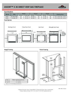
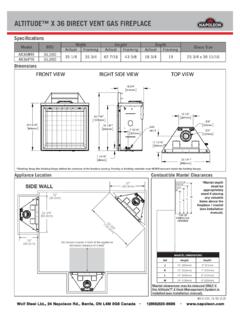
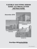
1 24 Napoleon Road, Barrie, Ontario, Canada L4M 0G8 214 Bayview Drive, Barrie, Ontario, Canada L4N 4Y8 Fireplaces, Heating and Cooling: 705-721-1212 Grills: 705 726-4278 50 DIRECT VENT LINEAR GAS APPLIANCEW415-1874 / A / cationsFront OptionsFraming DimensionsModelBTUW idthHeightDepthViewing AreaActualFramingActualFramingActualFram ingLV50N-236,00065 5/16 65 13/16 41 3/167319 7/820 1/852 3/4 X 18 5/8LV50N2-236,00065 5/16 65 13/16 41 3/167316 3/1616 3/1652 3/4 X 18 5/8single-sidedRefLV50-2E20 1/8 ( )F65 13/16 ( )JOptional - APPLIANCE does not need to be elevated above fl oor*L73 ( )EJFminimum framingLnote.
2 The LV series requires a minimum enclosure height of 73 measured from the bottom of the APPLIANCE . For temperature requirements, this area must be left unobstructed. Some venting confi gurations that require more vertical rise will require a larger enclosure to provide minimum vertical clearance between vent pipes and combustibles. note:Before framing the APPLIANCE , ensure to install the fi restop fi framing the APPLIANCE , ensure to install the fi restop fi rst as it will not fi t between the studs if installed after framing.
3 * Minimum enclosure height maybe higher depending on venting confi guration (see minimum distance to combustibles). RefLV50-2E16 3/16 ( )F65 13/16 ( )JOptional - APPLIANCE does not need to be elevated above fl oor*L73 ( )EFJminimum framingLnote:The LV series requires a minimum enclosure height of 73 measured from the bottom of the APPLIANCE . For temperature requirements, this area must be left unobstructed. Some venting confi gurations that require more vertical rise will require a larger enclosure to provide minimum vertical clearance between vent pipes and combustibles.
4 Note:Product information provided is not complete and is subject to change without notice. Please consult the installation manual for the most up to date installation "MAX ADJUSTMENTMIN. PROJECTION FROM FINISHING MATERIAL38"53716"4738"1934"121516"SLF50K /SSPSB50SS/K 17916" A 3612" 1418" 114" MAX. ADJUSTMENT1 NOTE 1" 51 7/8 48 1/2 24 Napoleon Road, Barrie, Ontario, Canada L4M 0G8 214 Bayview Drive, Barrie, Ontario, Canada L4N 4Y8 Fireplaces, Heating and Cooling: 705-721-1212 Grills: 705 726-4278 50 DIRECT VENT LINEAR GAS APPLIANCEP roduct information provided is not complete and is subject to change without notice.
5 Please consult the installation manual for the most up to date installation PenetrationAppliance LocationCombustible Mantel ClearancesLV50-2A(Finishing Flange)52 3/4 (1340mm)B 65 5/16 (1659mm)C69 5/16 (1761mm)*Finishing flange depth. (The finishing flange defines the perimeter of the fireplace opening. Framing or finishing materials must NEVER encroach inside the finishing flange.)single-sidedLV50-2A(Finishing Flange)52 3/4 (1340mm)B 65 5/16 (1659mm)C69 5/16 (1761mm)see-thrusingle-sidedThe LV series requires a minimum enclosure height of 73 ( ) measured from the bottom of the APPLIANCE .
6 For temperature requirements, this area must be left unobstructed. Some venting confi gurations that require more vertical rise will require a larger enclosure to provide minimum vertical clearance between vent pipes and :Horizontal vent sections: A minimum clearance of 3 (76mm) on the top outside of the enclosure and 2 (51mm) on the sides and bottom outside of the enclosure all around the vent pipe on all horizontal runs to combustibles is required. Horizontal vent sections within enclosures require a minimum clearance of 6 (152mm) at the top of the vent pipe.
7 Vertical vent sections: A minimum of 1 (25mm) all around the vent pipe on all vertical runs to combustibles is required except for clearances in appliances enclo-sures. Vertical vent sections within enclosures require a minimum clearance of 1 (25mm) around the vent pipe. see-thruHorizontal vent sections: A minimum clearance of 3 (76mm) on the top outside of the enclosure and 2 (51mm) on the sides and bottom outside of the enclosure all around the vent pipe on all horizontal runs to combustibles is required.
8 Horizontal vent sections within enclosures require a minimum clearance of 6 (152mm) at the top of the vent pipe. Vertical vent sections: A minimum of 1 (25mm) all around the vent pipe on all vertical runs to combustibles is required except for clearances in appliances enclosures. Vertical vent sections within enclosures require a minimum clearance of 1 (25mm) around the vent pipe. 0.+/-.:3'4:+2 MANTEL DEPTH12 3456789101124681012141618202224 ATop of finishing flangeBottom of the appliance25 11/16" ( )2 Bottom of fi nishing fl angeOptional hearth extension (no depth restriction)MANTEL HEIGHTMANTEL DEPTHLV50-2*E20 1/8 ( )F 65 13/16 ( )G72 1/4 ( )H18 3/16 ( )I102 3/16 ( )
9 Minimum framingW415-1874 / A / 3/16"1046mm 7 1/16"179mm 18 5/8"473mm 3 1/8"80mm 19 7/8"1/2 [ ]505mm 32 3/4"832mm 39 11/16"1008mm 8 1/16"205mm 8 1/16"205mm 8"203mm 5"127mm ABCSAFETY BARRIER*Base of air collarsee-thru(41 3/16"1046mm 7 1/16"179mm 18 5/8"473mm 3 1/8"80mm 32 3/4"832mm 39 11/16"1008mm 16 3/16"411mm 8 1/16"205mm 8 1/16"205mm 8"203mm 5"127mm 1/2"[ ]1/2"[ ]ABCSAFETY BARRIER**Base of air collarDo not put objects in front of the APPLIANCE (minimum distance of 4 feet)FGFHI*E1 ( ) ( ) min.)
10 *Single-sided model [76mm] top (outside of enclosure)2 [51mm] sides / bottom (outside of enclosure)0 to non-combustible fi nishing such as brick and stone6 [152mm] minimum(inside enclosure)0 to bottom of the appliance0 to side standoffs1/2 fi nishing fl angeWhen passing through a ceiling, use fi restop spacer W500-0028 (not supplied)When passing through a wall, use fi restop spacer W615-0162 (supplied with W010-4178 fi restop spacer assembly)0 to back standoffs1 [25mm] minimum all sides for sections of vertical [76mm] (minimum all sides for sections of horizontal vent-ing) outside of minimumThe LV series requires a minimum enclosure height of 73 ( ) measured from the bottom of the ap-pliance.