Transcription of Vehicle electrics in Polo Model Year 2002 - VolksPage.Net
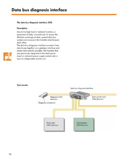
1 Service. Self-Study Programme 265. Vehicle electrics in Polo Model year 2002. 265_061. The range of electrical systems in new vehicles is expanding increasingly as a result of the ever more effective safety systems and enhanced convenience systems. The Vehicle electrics in the Polo Model year 2002 have been reorganised with the aim of retaining a clear arrangement within the comprehensive onboard power supply. A major role in this connection is played by a onboard power supply control unit. It monitors the capacity utilisation of the onboard power supply and performs functions which, until now, were executed by separate relays and control units. Moreover, the databus diagnostic interface, which permits data transfer between diffe- rent CAN databus systems, is also integrated in the onboard power supply control unit. NEW Important Note The Self-Study Programme describes the Please always refer to the relevant service design and function of new developments!
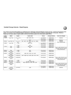
2 Literature for up-to-date inspection, adjustment The contents are not updated. and repair instructions. 2. At a glance Introduction .. 4. Onboard power supply .. 6. Onboard power supply control unit .. 13. Function diagram ..22. CAN databus ..24. Databus diagnostic interface ..26. Special functions ..30. Convenience and safety electronics ..32. Sliding/tilting roof .. 37. Dash panel insert ..38. Lighting ..42. Self-diagnosis..44. Test your knowledge ..46. 3. Introduction The Vehicle electrics of the Polo Model year Overview of control units in the Polo 2002 have been redesigned in terms of its concept and its structure. The onboard power supply control unit plays a central role in this connection. It performs a wide range of new check, monitoring and relay Radio or functions. Radio-navigation system The other control units are located decentralized within the Vehicle . In the pages which follow you will be able to familiarize yourself with the following subjects of the electrical system of the Polo Model year 2002: Design of onboard power supply Tasks and functions of onboard power supply control unit Design of CAN databus system ABS control unit Tasks of databus diagnostic interface Presentation of convenience and safety elec- tronics Design and functions of the dash panel insert Lighting concept Climatic/CLIMA tronic control unit Airbag control unit Power steering control unit 4.
3 Door control unit Sliding roof adjustment passenger side control unit Rear right door control unit Control unit with display unit in dash panel insert Rear left door control unit 265_013. Door control unit driver side Onboard power supply control unit with gateway Engine control unit Automatic gearbox Convenience system control unit central control unit 5. Onboard power supply Onboard power supply The onboard power supply is a decentralized design. The most important stations are: 265_006 265_007. Coupling stations in A-pillar and B-pillar L K I H D C B A. P N M G F E. 265_005. Compact connector 265_008. Fuse holder 265_012. 265_009. Main fuse carrier 1 2 3 4. 265_010 265_011. 5 6 7 8 9. Voltage distributor Onboard power 10 11 12 13 14 15. 265_021 supply control unit Relay carrier 6. Main fuse carrier The main fuse carrier is located on battery cover. The number of fuses always depends on the equipment fitted to the particular Model . The main fuse carrier houses up to 6 strip fuses and 10 plug-in fuses.
4 A voltage cable provides the connection to the battery (positive). The fuses protect the individual power circuits immediately downstream of the battery from overloads. 265_009. Voltage distributor The voltage distributor is located on the driver side behind the dash panel cover. The voltage distributor is responsible for distribu- ting the current of terminal +30 from the main fuse carrier on the battery to the individual elec- trical components. 265_010. 7. Onboard power supply Mini-fuse Fuse holder The fuse holder is located behind the cover in the left side of the dash panel. There are two types of fuses for protecting the power circuits: Mini-fuses up to 15 A. Little fuses more than 15 A. This combination offers the following advan- tages: greater number of fuses within the same space 265_008. Little fuse greater number of individually protected cir- cuits These fuses are identified in the current flow Position Relay diagram with the abbreviated designation SB.
5 1 Not assigned 2 Motronic power supply relay Relay carrier 3 Glow plug relay The relay carrier is located on the driver side 4 Fuel pump relay behind the dash panel cover. (diesel engines). 5 Entry warning light relay Compared to the design consisting of mini elec- trical centre and additional relay carrier, the 6 Headlight washer system relay relay carrier of the Polo is a single component 7 Starter lockout relay with standardized design for accommodating the relays. 8 Low heating capacity relay 9 High heating capacity relay 10 Simos control unit 1 2 3 4 power supply relay 11 Relief relay for X contact 5 6 7 8 9 12 Fuel supply relay 13 Fuel pump relay 10 11 12 13 14 15 (petrol engines). 14 Fuse carrier for electric auxiliary heater 265_021 15 Diesel direct injection system relay 8. Coupling stations The purpose of the coupling stations is to link the electrical components in the doors to the rest of the onboard power supply. The coupling stations permit: easy access separation of the wiring looms to the doors simplified fault finding A-pillar coupling station: It is located close to the top door hinge at the A-pillar.
6 This coupling station combines the plug connec- tions to the following electrical components in the doors: loudspeaker exterior mirror lock unit warning light 265_006. B-pillar coupling station: It is located close to the top door hinge of the rear door at the B-pillar. This coupling station combines the plug connec- tions to the following electrical components in the doors: loudspeaker lock unit 265_007. 9. Onboard power supply Compact connector The compact connector links the part of the The connection is created by means of the indivi- onboard power supply in the engine compart- dual connectors of the modules, irrespective of ment to the part of the onboard power supply in the equipment or version variants. the interior. The connector provides a straightforward means The onboard power supply is designed in such a of separating the onboard power supply at this way that all the cables of the components or the point. two wiring looms (engine compartment, interior) This greatly facilitates test operations as well as merge in their individual connectors of the removal and installation work.
7 Modules on the relevant side of the compact connector. Bulkhead Coupling stations Roof module Coupling connector Middle part of dash panel 265_022. Battery Coupling connector Compact connector Coupling station Fuse carrier 10. Design of the compact connector The compact connector is located in the left of the bulkhead, behind the wiper linkage. It is accessible from the engine compartment as well as from the interior. Compact connector View from engine compartment Partition wall connector Securing screws 265_075. View from interior Compact connector Lock for single connectors Single connector 265_076. 11. Onboard power supply The compact connector is subdivided into various modules. The connections are created by means of mechanically coded connectors of dif- ferent colours for the individual modules. Compact connector View from engine compartment L K I H D C B A. P N M G F E. 265_005. Connector assignment Module Responsible for Module Responsible for A ABS, ESP H Not assigned B Gearbox, engine, K wire, I Additional heater, accelerator pedal clutch pedal switch position sender, brake pedal switch C Engine power supply K Engine, dash panel insert D Light, cruise control system, L AC, radiator fan control drivetrain CAN databus E Anti-theft alarm system M ABS, ESP.
8 F Battery +30 N Diesel glow plug system G Dash panel insert P Windscreen wash and wipe system 12. Onboard power supply control unit Onboard power supply control unit Connector mount J519. Within the Vehicle onboard power supply, the control unit plays a central role. It has functions which were previously performed by separate relays and control units. The onboard power supply control unit performs the following functions: Load management Interior light control Fuel pump feed control Windscreen wash and wipe control, intermittent and rain sensor mode Exterior mirror and rear window heater Rear seat backrest monitoring 265_014. Turn signal and hazard warning light control Connector mount Horn control Cruise control system (supplying signals over Depending on the level of equipment, functions drivetrain CAN databus) of differing extent are integrated in the control Remote release of boot lid/tailgate unit. Consequently, there are also variations in Instrument and switch lighting the positioning of the connector mounts.
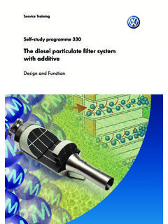
9 Maintaining operation of sliding roof and power windows Additional functions on models fitted with auto- matic gearbox: Implementation of the onboard power supply control unit has made it possible to cut Vehicle Actuation of selector lever lock solenoid weight by reducing the extent of wiring and plug Starter lockout connections as well as a number of relays and Actuation of reversing lights control units. Fitting location The onboard power supply control unit is posi- tioned on the driver side behind the dash panel cover. 265_015. 13. Onboard power supply control unit Load management The wide range of convenience functions and The load management of the onboard power electrically heated components such as seat hea- supply control unit regularly monitors the battery ter, rear window heater, exterior mirror heaters voltage, while taking into account the power and electric auxiliary heater (heating element for demand of short-term consumers. auxiliary heater Z35) can result in an overload of the alternator when driving and thus in a drain If it detects a voltage deficit in the onboard on the battery.
10 Power supply, the control unit initiates measures to maintain Vehicle operation and to ensure that This is particularly the case when driving extre- the Vehicle can be restarted. mely short distances and in winter as well as stop- and go journeys and vehicles with a high level of equipment. Electrical circuit G. C. A Battery C Alternator Engine control unit J131 Heated driver seat control unit J132 Heated passenger seat J .. A. control unit J255 CLIMA tronic control unit J301 AC control unit J519 Onboard power supply control unit J533 Databus diagnostic interface J533 J519. Z1 Heated rear window Z4 Heated exterior mirror, driver side Z5 Heated exterior mirror, J255/. passenger side J301 J131 J132. Z1 Z4 Z5. Z6 Heated driver seat Z7 Heated driver backrest Z8 Heated passenger seat Z9 Heated passenger backrest Z6 Z7 Z8 Z9. 265_046. 14. Idling speed is increased if onboard If specified voltage is again reached, onboard power supply voltage drops onboard power supply control unit below V.