Transcription of Verification of intrinsic safety - Electromach
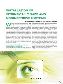
1 Verification of intrinsic safety Co and Lo parameters for mixed circuitsby Thomas Eichhorn, Ulrich Johannsmeyer, Anton Schimmele The intrinsic safety of an electrical circuit is essentially dependent on the safe limita-tion of current and voltage, and consequently of the power supplied, so that in neither normal operation nor under specified fault conditions ignition capable sparks can be produced by making or breaking circuits, or when there is a short-circuit to earth. To avoid spark ignition the energy stored in the circuit of course has to be limited. Even small amounts of additional energy can be sufficient to impair intrinsic safety . Besides spark ignition also thermal igni-tion due to hot surfaces must be avoided. Therefore it has to be ensured, that the maxi-mum current, voltage, and power available within the intrinsically safe circuit will not lead to unacceptably high surface tempera-Legislation, Standards and Technologyhazardous areasafe areamaximum outputvoltage and currentfrom the sourceEx iCCLCIOUO maximum capaci-tance and induc-tance allowedin the intrinsicallysafe circuitLOCO maximum powerof the source *)Pimaximum valuesof voltage andcurrent allowed forthe intrinsicallysafe apparatusIiUieffective internalcapacitance andinductance of theintrinsically safeapparatusLiCimaximum powerallowed for theintrinsically safeapparatusPOintrinsically safe apparatusIO_<IiUO_<UiLO_>Li + LcCO_>Ci + CcPO_<Pi*) with resistive current limitation PO= 1/4 UO x IOwith electronic current limitationPO= UO x IOassociated apparatusFigure 1.
2 Criteria for the Verification of a simple intrinsically safe circuittures at apparatus , components, and cables located in the hazardous area, in normal operation and under fault conditions. For compliance with these criteria not only the individual device, but also the com-plete interconnection and interoperation of all apparatus in the intrinsically safe circuit, including the connecting cables, must be considered. The Standard for electrical installations EN 60079-14 /IEC 60079-14 [1]consequently requires a Verification of intrin-sic safety for intrinsically safe circuits, which should ideally be carried out during planning and design, and includes the selection of apparatus , suitable for interconnection used. For simple intrinsically safe circuits with only one source supplying current, voltage and power to the circuit, Verification 60 | 61Ex-Magazine 2007 of in trinsic safety can easily be made by comparison of the safety values as shown in Figure 1.
3 Co and Lo parameters for intrinsically safe circuits with lumped capacitances and inductances (mixed circuits) Regarding the determination of the maxi-mum allowable values of capacitance and inductance in an intrinsically safe circuit a national (German) foreword in the Standard for electrical installations DIN EN 60079 -14 (VDE 0165-1): 1998-08[2] already mentioned that, the maximum external inductances Lo and capacitances Co marked on the asso-hazardous areasafe areatransmitter supply unitEx itransmitterindicatorlimit transducerfieldLNPELNPE controlroominstrumentpanel123I++ The circuit is a mixed circuitwith lumped Li and lumped Ci**Loop diagram of intrinsic safetyfor intrinsically safe circuits with one sourceAssociated apparatus (Source) 1 Transmitter supply unitIs reduction of Co and Lonecessary for mixed circuit?Intrinsically safe apparatus 2 Pressure transmitter 3 IndicatorCapacitance and inductance of cablesTotal:Protection level of intrinsically safe YesNo.
4 Manufacturer/type Test certificateNo. Manufacturer/type Test certificateFigure 2b: Verification of intrinsic safety for the circuit in 2aciated apparatus are not intended for simul-taneous use. Particularly when the intrin-sically safe circuits are used in Zone 0 and the devices contain lumped inductances and capacitances, which are both directly effec-tive to the circuit, PTB-Report PTB-W-39 [4] was recommended for the Verification of intrinsic safety . The reference to Zone 0 applications was even deleted from the national foreword to the next edition of the German version of DIN EN 60079-14 (VDE 0165 -1): 2004-07[3], thereby extending the requirement to all intrinsically safe cir-cuits. For the assessment now reference was given to the PTB report PTB-ThEx-10 [5] or Annex C of system standard EN 60079-25[6]. Verification of intrinsic safetyFigure 2 a: Example of a simple intrinsically safe circuit (with one source) In intrinsically safe circuits containing both capacitances and inductances, spark ignition can in fact be demonstrated even at L and C values that are lower than the lim-its calculated using the reference curves of EN 50020 [7] or EN 60079-11 [8].
5 This effect is caused by the dynamic interaction of the energy stored in capacitance and in-ductance. In extreme cases this effect can lead to a definite reduction of the safety fac-tor, making a separate evaluation necessary. However, this effect is particularly notice-able when the intrinsically safe circuit in-cludes lumped inductances and capacit-ances. Cable inductances and capacitances, on the other hand, are distributed along the entire length of the cable, and the conductor Figure 2 shows an example of an intrinsi - cally safe circuit with one associated appa-ratus (transmitter supply unit) and two in- trinsically safe apparatus (transmitter and indicator), together with the relevant verifica-tion of intrinsic safety . The transmitter has both an internal capacitance Ci and an inter-nal inductance Li. So here we have a mixed can such a mixed circuit, which con-tains both lumped capacitances and inductances, be assessed for the Verification of intrinsic safety ?
6 The first and easiest option is to find out whether the manufacturer of the associated apparatus (source) has perhaps already specified the Co and Lo values, which apply when lumped capacitances and inductances occur simultaneously. This has always been the case, for instance, with non-linear sources. Also for linear sources the type examination certificates or the operating in-structions sometimes specify reduced Coand Lo values, which can be used when the intrinsically safe circuit contains lumped ca-pacitances and inductances simultaneously. If this is not the case, then a second op-tion is to consult the new apparatus standard EN 60079-11 [8] for the assessment. For intrinsically safe circuits with linear sources this standard has incorporated simplified rules to determine reduced Co and Lo values for mixed circuits (see also Figure 3). According to this > the full values of Co and Lo can be utilised in circuits that only contain cable capaci-tances or cable inductances;> the full Co and Lo values can also be used in circuits where either only up to 1 % of the Co value is utilised by lumped capaci-tances Ci or only up to 1 % of the Lo value is utilised by lumped inductances Li.
7 > If Ci and Li are greater than this, half the value of Coand Lo can be utilised. The reduced Co value does of course apply as a limit value for the total of all ca pacitances in the intrinsically safe circuit ( the internal capacitances Ci of all de vices plus the cable capacitance). The same applies to the Lo per unit length considerably damp-ens the dynamic interaction. Consequently no special measures are required for circuits that only contain cable inductances and capacitances, i. e. the limits derived from the reference curves can be fully utilised. It is a different matter if the intrinsically safe circuit contains intrinsically safe appa-ratus, for which both internal capacitances Ciand internal inductances Li are effective. They can become effective in the intrinsically safe circuit directly without limitation through a resistive element. In the case of such mixed circuits we must assume that the limit values of Co and Lo need to be 3: Assessment rules for the reduction of Co and Lo values in the case of mixed circuits with linear sources in compliance with EN 60079-11: 01-2007full values of CO and LO can be utiliseduse reducedCO and LO valuesfor mixed circuitYLi = 0 NYCi = 0 NYLi_<1%of LONYCi_< 1%ofCONfor intrinsically safecircuits with linearsources: half thevalue of CO and LOcan be utilised62 | 63Ex-Magazine 2007 In the example shown in Figure 2 a the answer to the question Li < 1 % of Lo ?
8 Would have to be yes, with the consequence that the full values of Co and Lo can be utilised. A third option for determining the permis-sible Lo and Co values of mixed circuits would be to use PTB s ispark software or the limit diagrams shown in PTB report ThEx-10 [5], which were also incorporated in the system standard EN 60079-25 [6] as Annex C. This report describes a procedure for assessing interconnections involving several (linear or non-linear) sources. It contains a whole series of limit diagrams that differ in relation to the explosion group and the parameter first step is to select a limit diagram that is suitable for a particular application. Into that diagram the output characteristic for the intrinsically safe circuit is to be plot-ted and then it has to be checked graphically whether the characteristic curve does not exceed the limit curve for rectangular sourc-es at any point.
9 Furthermore, the maximum safety value pair (Uo, Io) shall not exceed the dashed limit curve for linear sources. For the permissible capacitance limits Cothere are two sets of curves with dashed and continuous lines. With these curves it has to be checked, which continuous capaci-tance curve is not exceeded at any stage by the characteristic curve and additionally under which dashed capacitance curve the value pair Uo and Io remains. The lower of the two established capacitance curves de-termines the maximum permissible capaci-tance in the intrinsically safe circuit that may occur simultaneously with the inductance specified for the selected limit diagram. The required safety factor of has already been incorporated in the diagrams. The Coand Lo values determined using this method also apply if lumped inductances and capacitances occur simultaneously in the intrinsically safe circuit, i.
10 E. the interaction of inductance and capacitance in a mixed circuit is taken into account. The limit diagram for explosion group IIC and an inductance of Lo = mH was select-ed for the example shown here. In this case the current-voltage characteristic for the linear source (transmitter supply unit) with the vertexes Uo = 27 V and Io = 88 mA has been plotted on the diagram (Figure 4). These maximum values must be checked against the dashed limit curves that apply to linear sources. The rectangle spanned above the maximum values remains below the dashed curve with the parameter value of 70 nF. Here the combination of Co = 70 nF and Lo = mH could be determined as permissible for the mixed circuit, and consequently the com-bination can now be entered in the documen-tation for the Verification of intrinsic safety . It is evident that a considerable reduction had to be applied compared with the Lo and Co values specified for the source.