Transcription of Very High CMR, Wide VCC Logic Gate Optocouplers
1 very high CMR, wide VCC LogicGate OptocouplersTechnical DataHCPL-2201 HCPL-2202 HCPL-2211 HCPL-2212 HCPL-2231 HCPL-2232 HCPL-0201 HCPL-0211 HCNW2201 HCNW2211 Features 10 kV/ s Minimum CommonMode Rejection (CMR) atVCM = 1000 V(HCPL-2211/2212/0211/2232, HCNW2211) wide Operating VCC to 20 Volts 300 ns Propagation DelayGuaranteed over the FullTemperature Range 5 Mbd Typical Signal Rate Low Input Current ( mAto mA) Hysteresis Totem Pole Output (NoPullup Resistor Required) Available in 8-Pin DIP,SOIC-8, Widebody Packages Guaranteed Performancefrom -40 C to 85 C Safety ApprovalUL Recognized -2500 V rmsfor 1 minute (5000 V rmsfor 1 minute forHCNW22XX) per UL1577 CSA ApprovedVDE 0884 Approved withVIORM= 630 V peak (HCPL-2211/2212 Option 060 only)and VIORM= 1414 V peak(HCNW22XX only)BSI Certified (HCNW22 XXonly) MIL-STD-1772 VersionAvailable(HCPL-52XX/62XX)
2 Applications Isolation of high SpeedLogic Systems Computer-PeripheralInterfaces Microprocessor SystemInterfaces Ground Loop Elimination Pulse TransformerReplacement high Speed Line Receiver Power Control SystemsDescriptionThe HCPL-22XX, HCPL-02XX,and HCNW22XX are optically-coupled Logic gates. TheHCPL-22XX, and HCPL-02 XXcontain a GaAsP LED while theHCNW22XX contains an AlGaAsLED. The detectors have totempole output stages and opticalreceiver input stages with built-inSchmitt triggers to provide Logic -compatible waveforms, eliminat-ing the need for superior internal shield on theHCPL-2211/12, HCPL-0211,CAUTION.
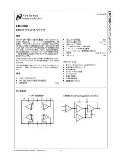
3 It is advised that normal static precautions be taken in handling and assembly of this componentto prevent damage and/or degradation which may be induced by DiagramA F bypass capacitor must be connected between pins 5 and HCPL-0201/11 HCNW2201/1171234568 NCANODECATHODENCGNDVCCVONCSHIELDHCPL-220 2/1271234568 ANODE 1 CATHODE 1 CATHODE 2 ANODE 2 GNDVCCVO1VO2 SHIELDHCPL-2231/32 TRUTH TABLE (POSITIVE Logic )LED ON OFFVO high LOW2 Selection GuideSmall-WidebodyMinimum CMRI nput8-Pin DIP (300 Mil)Outline SO-8(400 Mil)HermeticOn-SingleDualSingleSingleSin gle anddV/dtCurrentChannelChannelChannelChan nelDual Channel(V/ s) VCM (V)(mA)PackagePackagePackagePackagePacka ges1, [1,2] , [1,2]5,000[3]300[3] , [2]HCPL-62XX[2]Notes:1.
4 HCPL-2200/2219 devices include output enable/disable Technical data for the HCPL-2200/2219, HCPL-52XX and HCPL-62XX are on separate HP Minimum CMR of 10 kV/ s with VCM = 1000 V can be achieved with input current, IF, of 5 InformationSpecify Part Number followed by Option Number (if desired).Example:HCPL-2211#XXX060 = VDE 0884 VIORM = 630 V peak Option*300 = Gull Wing Surface Mount Option**500 = Tape and Reel Packaging OptionOption data sheets available. Contact your Hewlett-Packard sales representative or authorized distributor forinformation.
5 *For HCPL-2211/2212 only.**Gull wing surface mount option applies to through hole parts HCPL-0201/11 HCNW2201/11 IFSHIELDVFVCCVOGNDICCIO+ 2385IF1 SHIELDVF1 VCCVO1 ICCIO1+ 1286 HCPL-2231/32 SHIELDVF2VO2 GNDIO2 +345IF27 HCPL-2232 and HCNW2211guarantees common modetransient immunity of 10 kV/ s ata common mode voltage of electrical and switchingcharacteristics of the HCPL-22XX, HCPL-02XX andHCNW22XX are guaranteed from-40 C to +85 C and a VCC volts to 20 volts. Low IF andwide VCC range allow compatibil-ity with TTL, LSTTL, and CMOS Logic and result in lower powerconsumption compared to otherhigh speed couplers.
6 Logic signalsare transmitted with a typicalpropagation delay of 150 ( ) ( ) ( ) ( ) ( ) ( ) + ( + )- ) ( ) ( ) ( ) ( ) ( ) XXXXZYYWWDATE CODEDIMENSIONS IN MILLIMETERS AND (INCHES).56784321 OPTION CODE*ULRECOGNITIONURTYPE NUMBER*MARKING CODE LETTER FOR OPTION NUMBERS"V" = OPTION 060 OPTION NUMBERS 300 AND 500 NOT Outline Drawings8-Pin DIP Package (HCPL-2201/02/11/12/31/32)8-Pin DIP Package with Gull Wing Surface Mount Option 300 (HCPL-2201/02/11/12/31/32) ( )12 ( ) ( ) ( ) ( ) ( ) ( ) ( ) ( ) ( ) ( ) ( ) ( ) ( ) ( )PAD LOCATION (FOR REFERENCE ONLY) ( ) ( ) ( ) ( ) ( ) BSCDIMENSIONS IN MILLIMETERS (INCHES)
7 LEAD COPLANARITY = mm ( INCHES). + - ( + ) - )4 Small-Outline SO-8 Package (HCPL-0201/11)8-Pin Widebody DIP Package (HCNW2201/11) ( ) ( ) ( ) ( ) ( ) IN MILLIMETERS (INCHES).7 + - ( + ) - ) ( ) ( ) ( ) HCNWXXXX YYWWDATE CODETYPE ( ) ( ) ( ) ( ) ( )XXX ( ) ( ) ( ) ( ) ( ) ( ) ( )45 ( ) ( )TYPE NUMBER (LAST 3 DIGITS)DATE ( ) PACKAGE LENGTH (INCLUSIVE OF MOLD FLASH) ( ) DIMENSIONS IN MILLIMETERS (INCHES).
8 LEAD COPLANARITY = mm ( INCHES) ( )7 PIN ONE0 ~ 7 **58-Pin Widebody DIP Package with Gull Wing Surface Mount Option 300 (HCNW2201/11)Note: Use of nonchlorine activated fluxes is highly T = 115 C, C/SEC0 T = 100 C, C/SEC T = 145 C, 1 C/SECTIME MINUTESTEMPERATURE C220200180160140120100806040200260123 456789101112 Solder Reflow Temperature Profile (HCPL-02XX and Gull Wing Surface Mount Option 300 Parts) ( )7 ( ) ( ) ( ) ( ) ( ) ( ) ( ) ( ) ( )PAD LOCATION (FOR REFERENCE ONLY) ( ) ( ) ( ) ( ) BSCDIMENSIONS IN MILLIMETERS (INCHES).
9 LEAD COPLANARITY = mm ( INCHES). + - ( + ) - ) InformationThe HCPL-22XX/02XX andHCNW22XX have been approvedby the following organizations:ULRecognized under UL 1577,Component RecognitionProgram, File under CSA ComponentAcceptance Notice #5, File according to VDE0884 (HCPL-2211/2212 Option 060 and HCNW22XX only)BSIC ertification according toBS415:1994,(BS EN60065:1994);BS EN60950:1992(BS7002:1992) andEN41003:1993 for Class IIapplications. (HCNW22XX only)Insulation and Safety Related Specifications8-pin DIP Package8-Pin DIPW idebody (300 Mil)SO-8(400 Mil)Parameter SymbolValueValueValueUnitsConditionsMini mum ExternalL(101) from input terminalsAir Gap (Externalto output terminals, shortestClearance)distance through ExternalL(102) from input terminalsTracking (Externalto output terminals, shortestCreepage)distance path along insulation distance,Plastic Gapconductor to conductor, usually(Internal Clearance)
10 The direct distance between thephotoemitter and photodetectorinside the optocoupler from input terminalsTracking (Internalto output terminals, alongCreepage)internal ResistanceCTI200200200 VoltsDIN IEC 112/VDE 0303 Part 1(ComparativeTracking Index)Isolation GroupIIIaIIIaIIIaMaterial Group(DIN VDE 0110, 1/89, Table 1)Option 300 - surface mount classification is Class A in accordance with CECC 0884 Insulation Related Characteristics(HCPL-2211/2212 Option 060 ONLY)DescriptionSymbolCharacteristicUnit sInstallation classification per DIN VDE 0110 , Table 1for rated mains voltage 300 V rmsI-IVfor rated mains voltage 450 V rmsI-IIIC limatic Classification55/85/21 Pollution Degree (DIN VDE 0110 )


