Transcription of VIBROCONTROL 920 - bruel.hu
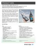
1 VIBROCONTROL 920 Reliable prevention of machine damageDuring operation, machines are subjected to a number of influences which change the condition of rotating parts, bearings, machine housing and foundations and may result in costly damage or secondary defects. The most common causes of damage are: Unbalanced rotating parts as a result of manufacturing errors, material defects and normal wear Unbalance due to deposits on the blades of exhaust fans, blowers and air separators Unbalance due to asymmetric load- ing of centrifuges and separators Unbalance due to eccentric wind- ing of wire coils Alignment errors due to assembly faults, thermal growth in bearing supports or foundation movement Damaged roller bearings or gear mechanisms as a result of wear, ageing or overloadingAlmost all causes of damage affect the smooth operation of machines and lead to increased mechanical vibrations.
2 Vibrations are thus a reliable indicator of the condition of the individual machine elements and also the entire monitoringMeasurement of bearing vibration is performed in accordance with the ISO standard 10816. Vibration occurring at the machine surface is converted into electrical signals, which in turn are used to establish the RMS value of the vibration machine condition parameter is continuously compared with two preset limit values. If these limit values are exceeded, the switching contacts of allocated relays trigger an alarm or shutdown of the to the permanent monitoring, changes in the machine condition can be reliably identified, regardless of whether they are continuous ( due to wear) or intermittent/erratic ( due to sudden material failure or sudden peeling away of material deposited on the rotor).Electronic control unitThe electronic control unit is integra-ted in a plastic housing and is in-tended for use in a control cabinet.
3 The unit is mounted by either clipping it onto a standardised profile rail or screwing it to a mounting plate inside the control sensorThe vibration sensor converts the vibration occurring at the machine surface into electrical signals. Vibra-tion velocity or acceleration sensors can also be connected. The sensor is screwed to the machine housing, preferably at a point of support, and connected to the electronic control connecting cable, which is either 5 m or 10 m in length, depending on the sensor type, can be extended a further 300 m. Signal cable and termi-nal protective housings are available as options. VIBROCONTROL 920 Parameter configurationThe electronic control unit is config-ured interactively at the device with the Outstanding price/ performance ratio Simple and cost-saving installation Interactive parameter configuration via display - Measuring range - Frequency - Limit values - Relay time delays - Closed-circuit or open-circuit operation - Analogue outputs Signalling of limit value opera- tions by two relays with change-over contacts Display of measured value and limit violation at the monitoring device Analogue output for the connection of diagnostic devices Buffered output for the connection of diagnostic devices Self-monitoring of power supply and vibration pick-up Use of vibration velocity or accel- eration sensors Vibration pick-up for explosion- endangered areas can be connectedVIBROCONTROL 920 Specifications1)
4 Only with acceleration sensor with constant current supply (CCS)Order code VC-920 InputsNo. of vibration channels 1 Sensor connections Acceleration sensor, AS-022, AS-062 (CCS), ASA-022, etc. Velocity sensor, VS-068, VS-069, VS-0168, VS-0169 Sensor power -24 V DC (max. 30 mA) or 4 mA constant-current supply (CCS) 1) Velocity sensor: no power requiredSensor OK monitoring YesMeasured parametersMeasurement channel 1-channel operation with continuous monitoringMeasuring ranges Vibration velocity: 0 .. 10/20/50/100 mm/sFrequency 1/10 .. 1000 HzBearing vibration measurement RMS value of vibration velocity in mm/sMeasurement accuracy 5% of the measured valueMonitoringAlarm signalling Alert and danger alarm, adjustable between 0 and measuring range full scale valueRelay delay times 0 .. 100 sec. in steps of 1 sec for alert and danger alarmsLimit relays 2 relays, closed-circuit and open-circuit connection, latching or non-latchingSelf-monitoring OK fault signalling with separate OK relaySignalling display OK fault with green LED Limit violations: LIM 1 yellow LED, LIM 2 red LEDO utputsAnalogue signal outputs 0/4.
5 20 mA, load < 500 or 0 .. 10 V (load resistance RL > 10 k )Power supplyMains outlet 230/115 V AC, +/- 15%, 50 .. 60 Hz, approx. 12 VA 24 V DC (18 .. 32 V DC), approx. 7 WEnvironmental conditionsOperating temperature range 0 C .. +50 CStorage temperature range -10 C .. +70 CMechanical designHousing Plastic housing, protection class IP 20, total weight approx. 900 gDimensions 150 x 78 x 115 mm (W x H x D)DIN10816 ISOBr el & Kj r Vibro GmbH Leydheckerstra e 1064293 Darmstadt GermanyTel.: +49 (0) 6151 428 11 00 Fax: +49 (0) 6151 428 12 00 Br el & Kj r Vibro A/SSkodsborgvej 307B2850 N rumDenmarkTel.: +45 77 41 25 00 Fax: +45 45 80 29 of delivery and order information1. Electronic control unitconsisting of:1 VIBROCONTROL 920 vibration monitoring device with2 user manuals in German, English or French (please specify the language when ordering).
6 2. Vibration sensorAcceleration sensor AS-022 Any measurementstandard design direction, radial cable exit, 5 m, PVDF cable with open ends AS-030 Any measurement direction, axial cable connection, with FASTON plug terminalAcceleration sensor ASA-022 1) Any measurementin Ex design 1) direction, 5 m cable, Ex only when used with AC-293 safety barrier set AC-293 Safety barrier set for acceleration sensor ASA-022 Vibration velocity sensor VS-068 For horizontalstandard design measurement, 2-wire lead, PTFE, 5 m cable with steel protective conduit TA -40 C .. +80 C, 2) VS-069 For vertical measurement, 2-wire lead, PTFE, 5 m cable with steel protective conduit, TA -40 C .. +80 C, 2)Vibration velocity sensor VS-0168 For horizontalin Ex design measurement, 3-wire lead, PVC, 10 m cable TA -10 C .. +65 C, 2) VS-0169 For vertical measurement, 3-wire lead, PVC, 10 m cable TA -10 C.
7 +65 C, 2)3. Terminal protective housingRugged aluminium housing in IP 65 protection class, paintedRAL 7001, with cable design AC-2104 For max. 2 vibration sensors VS-068/069 or AS-022/030 Weight approx. kgEx design AC-2105 For max. 2 acceleration sensors, ASA-022 1), Weight approx. 600 g AC-2103 For max. 2 vibration velocity sensors, VS-0168, VS-0169, Weight approx. 650 g4. Signal cableStandard design AC-112 For vibration sensors AS-022/030 and VS-068/069, 4 x mm , shielded, PVC black LIY (ST) Y, 7 mm TA -20 C .. +70 C, 2)Ex design AC-114 For acceleration sensors, ASA-022 1), 4 x mm shielded, PVC blue, Li2Y-St / C-Y, 7 mm TA -25 C .. +70 C, 2) AC-180 For vibration velocity sensors, VS-0168/VS-0169 1), 3 x mm shielded, PVC grey (N) YLHCY-J, 7 mm TA -10 C .. +80 C, 2)1) ATEX certification and data sheets are available for download from our website2) TA operating temperature range10 / Status 0610 o All information non-binding.
8 Right of alteration reserved Design: BBR 0030-EN-02