Transcription of Vickers CG2V-10, CG5V-10 Pressure Relief Valves ... - Eaton
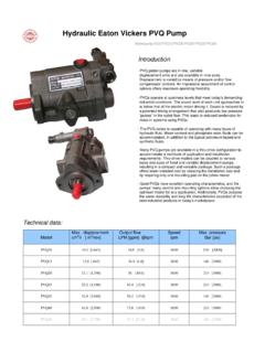
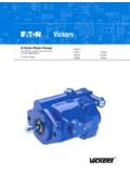
1 CG2V-10, CG5V-10 . Vickers 350 Bar Pressure Relief Valves Subplate Mount Table of Contents General 2. Functional 3. Model 4. Technical 5. Flow 5. 6. Application 7. Released Part 7. 1 Eaton Vickers Pressure Relief Valves V-VLSU-MC001-E December 2008. General Information Features limitation (CG2V) or pilot control valve (2). If the Now the Pressure fluid limitation and solenoid Pressure in port P exceeds flows from port P to port T. Subplate mounting actuated unloading ( cg5v ) the valve set at the spring whilst maintaining the set Porting pattern to DIN 24 of the control Pressure . (9), the ball (8) opens against operating Pressure .
2 340, form E,ISO 6264, the spring (9). CETOP-RP 121H and The Pressure Relief Valves The Pressure Relief valve NFPA/ANSI (CG2V) consist mainly of The signal for this comes may be unloaded or the main valve (1) with internally via the control switched over to a different Three adjustment main spool assembly (3) lines (10) and (6) from port Pressure (second Pressure elements: and pilot operated valve (2) P. The Pressure fluid on the stage) via port Rotary knob with Pressure adjustment spring loaded side of the X (15). Hex. head screw with element. main spool (3) now flows via protective cap the control line (7), orifice Pressure Relief valve type Lockable rotary knob Pressure Relief valve type bore (11) and ball (8) into the cg5v .
3 With scale CG2V spring chamber (12). In type The function of this valve is CG2V it flows internally via Solenoid operated The Pressure present in port basically same as the valve the control line (13) to tank, unloading P acts on the main spool (3). type CG2V. or in type At the same time Pressure externally via the control The unloading at the main General is applied via the control line (14). Due to the orifices spool (3), however, is lines (6) and (7), which are CG2V and cg5v Pressure (4) and (5) a Pressure drop acheived by the built-in fitted with orifices (4) and Valves are pilot operated occurs at the main spool (3), directional valve (16).
4 (5), on the spring loaded Pressure Relief Valves . the connection from port P. side of the main spool (3). They are used for the to port T is open. and at the ball (8) in the P T. P T. P T. P T. Eaton Vickers Pressure Relief Valves V-VLSU-MC001-E December 2008 2. Functional Symbols CG2V X Y XY. P P P. P. X X. Y Y. T T T T. cg5v cg5v cg5v cg5v . Normally closed Normally closed Normally closed Normally closed P P P P. A B A B A B A B. T P T X P T P T P T. T T T. X. Y Y. Normally open Normally open Normally open Normally open A B A B A B A B. P T P T P T P T. 3 Eaton Vickers Pressure Relief Valves V-VLSU-MC001-E December 2008.
5 Series CG2V. Model Code (F3) C. G2V 10 * * (*) (*) (*) 10 1 2 3 4 5 6 7 8 9. 1 -Ring Material O 3 . Size 5.. Adjustment 8 Pilot & Drain Blank Nitrile ISO6264-10 Wrench and cover W Blank Internal Pilot & Drain F3 Fluorocarbon NFPA/ANSI R10 H Knob X Internal Drain, 10 - Cetop 10 K Lockable knob External Pilot 2 ubplate Mounted S Y Internal Pilot, Relief Valve 4 Pressure Range 6 Port Thread External Drain B 50 bar F Metric XY External Pilot & Drain C 100 bar B BSP. F 200 bar 9 Design Number G 315 bar 7. Cracking Pressure H 350 bar Blank Standard 10. U Minimum (not available with 350 bar range). Series cg5v .
6 Model Code (F3) cg5v 10 * * (*) (U) (*) (*) 1 M U H7 10 1 2 3 4 5 6 7 8 9 10 11 12 13 14. 1 O-Ring Material 6 External Connection 10 Valve State 13 Coil Voltage Blank Nitrile F Metric 1 Normally Closed H7 24 VDC. F3 Fluorocarbon B BSP 2 Normally Open G7 12 VDC. B6 110V50Hz/120V60Hz 2 ubplate Mounted S 7 . Minimum Cracking 11 Flag D6 220V50Hz/240V60Hz Relief Valve with Pressure M. unloading function Blank Standard 14 Design Number U Minimum Cracking 12. Connector 3 Size Pressure (not available 10. U No Connector ISO6264-10 with 350 bar range) U1 Connector included NFPA/ANSI R10 U6 Connector with lights 10 - Cetop 10 8 Pilot & Drain FTWL Box with lights and lank Internal Pilot & Drain B 1/2 NPT conduit thread 4 Pressure Range X Internal Drain, External B 50 bar Pilot C 100 bar Y Internal Pilot, External F 200 bar Drain G 315 bar XY External Pilot & Drain H 350 bar 9 Pilot Override 5.
7 Adjustment lank Manual Override B. Wrench and cover W Z No Manual Override H Knob H Weatherproof K Lockable knob Eaton Vickers Pressure Relief Valves V-VLSU-MC001-E December 2008 4. Series CG2V. Technical Data Hydraulic Technical Data Maximum operating Pressure up to 350 (port P, X); 315 (port T). at ports P, T, X (Bar). Maximum back Pressure at port Y CG2V (Bar) up to 315. cg5v (Bar) up to 210. Pressure Range Minimum (Bar) flow dependent (see flow curves ). Maximum (Bar) 50, 100, 200, 315, 350. Weight CG2V Kg cg5v Kg Maximum Flow 650 Lpm Fluid Mineral oil (for Nitrile seal) or phosphate ester (for Fluorocarbon seal).
8 Fluid temperature range (OC) -30 to + 80 (Temperature limit for DG4V3 is 70oC). Fluid Viscosity range (mm2/s) 10 to 800. Fluid Cleanliness Level ISO 19/17/14. Flow Curves Inlet Pressure vs. flow (measured at v = 41. mm2/s and t = 50 OC) 400. Inlet Pressure vs. flow 350. in bar in bar 310. 400. 300. The characteristic curves Inlet Pressure vs. flow size 10. 350. bar Pressure 250. were measured with 310. 400. 200. 300. pilot externally drained. 350 size 10. 150. Inlet Pressure 250. 310. inInlet 300. 100. 200 size 10. For internal pilot oil drain Inlet Pressure 250. 50. 150. the inlet Pressure incre- 200.
9 100. ase by the outlet pres- 1500. 50. 100 200 250 300 400 500 600 650. sure present at port T. 100 flow in L/min 500 100 200 250 300 400 500 600 650. * The characteristic 0 100. flow in L/min 200 250 300 400 500 600 650. curves are valid for flowbypass Minimum controllable Pressure and in L/min Pressure in relation to the flow. *. outlet Pressure T = 0. over the entire flow 12. in bar in bar Minimum controllable Pressure and bypass Pressure in relation to the flow. *. range! 10. size 10. in bar Pressure 12. Minimum 08 controllable Pressure and bypass Pressure in relation to the flow. *. size 10. 10.
10 06. Pressure 12. controllable 08. 04 size 10. 10. Pressure 06. 02. 08. Min. controllable 04. Min. 06. 0 100 200 250 300 400 500 600 650. 02. Min. controllable 04. flow in L/min 02. 0 100 200 250 300 400 500 600 650. 0 100 flow 200 250 in L/min400. 300 500 600 650. flow in Pressure Minimum controllable Pressure and bypass L/min in relation to the flow Version U *. in bar in bar 12. Minimum controllable Pressure and bypass Pressure in relation to the flow size Version 10 U *. 10. in bar Pressure 12. Minimum08. controllable Pressure and bypass Pressure in relation to the flow Version U *. size 10. 10.