Transcription of Vickers Directional Controls Pilot Operated Directional ...
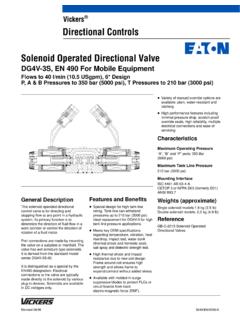
1 Pilot OperatedDirectional control ValvesDG5S4-04-60/70 NFPA D07, ISO-4401-07673 Released 3/94 Vickers Directional Controls2 Table of ContentsDG5S4-04 Model Code4.. General Information6.. Basic CharacteristicsShifting ActionMounting PositionApplicationInstallation DataOptional Features7.. Functional SymbolsService InformationModels & Graphical Symbols8.. Pressure Drop9.. Flow Ratings10.. Installation Dimension11.. Subplates & Bolt Kits13.. Electrical Information14.. Application Data18.. 3 IntroductionDG5S4-04 models are two-stagedirectional valves having an integrallymounted DG4V-3(S)-60 Pilot valves are generally used tocontrol the direction of flow in ahydraulic circuit. This in turn wouldcontrol the movement of a work cylinderor the rotation of a fluid and Benefits Suitable for the most demandingindustrial applications with flowcapacities up to 227 l/min (60 USgpm)and rated pressure of 210 bar (3000 psi).
2 Available with a wide variety of spooland spring arrangements, stroke andpilot choke adjustments, integral checkvalves, and port orifices. Solid cast body with cored passagesfor maximum strength and minimalpressure drop. Designed and manufactured byVickers, with over 70 years as theglobal leader in fluid power and CodePilot Operated Directional Valves45698711231213141516171819202112 Special sealsF3 -For mineral oil and fire resistantfluids Blank - Omit if not requiredDirectional control valveManifold or subplate mounting, solenoidcontrolled, Pilot Operated , sliding spool,rated pressure 210 bar (3000 psi)Interface04 - NFPA-D07 (ISO-4401-07)Spool types0, 2, 3, 4, 6, 8, 9, 31, 33 See models & graphic symbols table for arrangementA -Spring offsetB -Spring centered with solenoid A removedC -Spring centeredF - Shift to center from offset (single solenoid)N -No-spring detented ( Pilot only)Left-Hand assemblyL - Single solenoid models only.
3 Omit forright-hand assembly. (For right-handassembly P to A when solenoid a isenergized.)Manual override optionsBlank - Plain override solenoid end onlyH - Waterproof override solenoid ends onlyH2 - Waterproof override both ends of single solenoidP2 - Plain override both ends of -Lockable manual overridessolenoid ends only/DC onlyZ -No overrides in either end3456789101415 Response typeX - Fast responseBlank - Standard low shock modelsSpool control modifications1 -Stroke adjustments, both ends2 - Pilot choke (dual) adjustments3 - Pilot choke and stroke adjustments7 -Stroke adjustment A port end only8 -Stroke adjustment B port end only2-7 - Dual Pilot choke & strokeadjustment A port end only2-8 - Dual Pilot choke & strokeadjustment B port end onlyBlank - Omit if not requiredPilot pressureE -External Pilot pressureBlank - Internal Pilot pressurePilot drainT - Internal Pilot drainBlank - External Pilot drainPressure port check valveK -0,35 bar (5 psi) cracking pressureR - 3,4 bar (50 psi) cracking pressureS -5,2 bar (75 psi) cracking pressureBlank - Omit if not requiredSolenoid energization identityV -Solenoid identification determined byposition of solenoid (solenoid A at port A end and/or solenoid B at port B end)Blank - Standard arrangement for (energize solenoid A for flow P to A port)(Code V for any valve with code 4 orcode 8 spool)
4 Flag symbolM - Electrical options and featuresSpool indicator switch(Available on models with highperformance Pilot DG4V3 only)S3 - Normally open (available on valveswith code P* only)S4 - Normally closed (available onvalves with code P* only)S5 - Free leads (available on valves withcoil type code F only)S6 - LVDT type DC switch with Pg7connector plugCoil typeU -ISO 4400F -Flying leadSP1 - Single 6,3 mm spade to IEC 760SP2 - Dual 6,3 mm spade to IEC 760 Electrical connections(Code F coil only)T -Wired terminal blockPA -Insta-plug male receptacle onlyPB -Insta-plug male & femalereceptaclePA3 - NFPA 3-pin connectorPA5 - NFPA 5-pin connectorBlank - Omit if not requiredHousing(Code F coil only)W -1/2 NPT thread wiring housingJ -20 mm thread wiring housingBlank - Omit if not requiredSolenoid indicator lights(Code F coil w/Code T electricalconnections only)L - Indicator lightsBlank - Omit if not required1112131617182223110195 Model Code cont dCoil identificationA -110V/50 HzB -110V/50 Hz, 120V/60 HzC - 220V/50 HzD - 230V/50 Hz, 240V/60 HzG - 12V DCH - 24V DCDJ - 98V DCP -110V DCPilot valve tank pressure rating2 - 10 bar (145 psi) DG4V3-60 with S3,S4, or S5 spool indicator switch4 - 70 bar (1000 psi) hazardous model5 - 100 bar (1450 psi) DG4V3S-606 - 160 bar (2285 psi) DG4V3-60 with AC solenoids and optional S6 spoolindicator switch6 - 210 bar (3000 psi) DG4V3-60 with DC solenoids and optional S6 spoolindicator switch222320 Pilot valve port orificesCodeOrifice Diameter*00 -Solid plug*03 -0,30 mm ( in)*06 -0,60 mm ( in)
5 *08 -0,80 mm ( in)*10 -1,00 mm ( in)*13 -1,30 mm ( in)*15 -1,50 mm ( in)*20 -2,00 mm ( in)*23 -2,30 mm ( in)Blank - Omit if not required(* = P, T, A, and/or B as required)Design numberSubject to change. Installationdimensions remain as shown for designs60 through 69 and 70 through - DG4V3S-60 Pilot valve70 - DG4V3-60 Pilot valveRefer to GBC 2010 for more informationon the Pilot control InformationBasic CharacteristicsMax. pressure:210 bar (3000 psi)Max. flow:227 l/min (60 USgpm).. Max. pressure port T (external drain):210 bar (3000 psi).. Max. pressure port T (internal drain):DG4V-3S100 bar (1450 psi).. DG4V-3210 bar (3000 psi).. Max. Pilot pressure:210 bar (3000 psi).. Weights - See installation InterfaceISO-4401-07 NFPA D07 Shifting ActionSpring centered, pressure centered andspring offset models must be energizedcontinuously to maintain the shiftedposition.
6 Detented no-spring modelsmay be energized momentarily(approximately second).Pressure centered and spring centeredmodels return valve spool to centerposition when solenoids offset models return spool tooffset position by Pilot pressure whensolenoid is no-spring detented models arede-energized, the Pilot and main spoolsremain in the last position attained,provided there is no shock, vibration,unusual pressure transients and thespool axis is horizontal. If Pilot pressurefails or falls below the minimum, themain spool will spring center (at springcentered flow rates) and cannot drift toreverse flow ( Pilot stage remains indetented position).CAUTIONS urges of oil in a common tank lineserving these and other valves canbe of sufficient magnitude to causeinadvertent shifting of these is particularly critical in theno-spring detented type tank lines or a ventedmanifold with a continuousdownward path to tank is necessary.
7 (This also applies to connection X onspring offset valves , if X is piped asa drain.)NOTEAny sliding spool valve, if held forlong periods of time, may stick andnot spring return due to fluid residueformation and therefore, should becycled periodically to prevent thisfrom used as other than a normal4-way valve, consult your PositionNo-spring detented valves must beinstalled with the longitudinal axishorizontal for good machine mounting position of spring offsetmodels is unrestricted provided that thepilot pressure supply is maintained asrequired. (Spring offset valves do nothave a spring in the main spool section.)ApplicationAll spools at zero flow require 5,2 bar(75 psi) minimum Pilot pressure. Atmaximum flow without malfunction 5,5bar (80 psi) is required for open centerspools (types 0, 4, 8 & 9) and 8,6 bar(125 psi) is required for closed centerspools (types 2, 3, 6, 31 & 33).
8 NOTEThe Pilot pressure stated is basedon internally piloted and externallydrained models in which the pilotpressure is equal to the pressure atthe valve pressure port. With modelshaving pressure open or partiallyopen to tank at center position, pilotpressure can be assured byimposing a back pressure of at leastthe required minimum Pilot pressureat the tank outlet connection (thisback pressure will be present atcylinder ports if spool is 0 or 9 type). When Pilot pressure fromseparate source (external) isrequired, an external connection canbe provided. Order according tomodel DataPilot Valve DrainInternal: To provide maximum flowwithout malfunction, Pilot pressure ofinternally drained valves must alwaysexceed tank line back pressure by aminimum of 5,2 bar (75 psi) for spooltypes 0, 4, 8 & 9 and a minimum of 10,3bar (150 psi) for all other drain may be used with allvalves, however, an integral pressureport check valve (ref.)
9 Integral checkvalve on page 5) is required for valvesusing an internal Pilot source with anopen center spool (0, 4, 8 and 9 types)in order to maintain Pilot pressure. If anexternal Pilot source is used, an integralcheck is not required. When internalpilot drain is required, order according tomodel code. (Pressure centered valvesnot included.)External: When the possibility ofpressure surges in the tank line exists,externally drained valves arerecommended. For externally drainedmodels, the Pilot valve drain line mustbe piped directly to tank through a surgefree line so there will be no backpressure at this drain. (Referenceconnection Y .)7 Optional Features/Functional SymbolsPressure Centered Drain (external only)The external Pilot drain explanation onthe previous page applies to Y drainport. Pressure centered W drainconnection must be piped directly totank through a surge free line so therewill be no back pressure at this FeaturesIntegral Check ValveFor open center spools - When usinginternal Pilot pressure and internal pilotdrain, select appropriate check springmodel (K, R or S) from Pressure DropAcross Check Valve curve on page pressure drop required is 5,2 bar(75 psi), (see Pilot pressure ratings andnote) therefore, determine valve P (Pto T) at the actual application flow this value from 5,2 bar (75 psi)and call its value C.
10 Refer to the checkvalve pressure drop curve at theapplication flow rate and select thespring model letter whose curve isabove this pressure (bar/psi) value C .Fast ResponseUse of this option decreases shift timeapproximately 60%. However, systemshock generation is correspondinglyincreased. The fast response option isnot recommended for Pilot pressureexceeding 138 bar (2000 psi).Service InformationRefer to specific Vickers parts drawingfor service parts information. A completeparts breakdown is contained in thisdrawing. Order by literature .. Typical shift times in milliseconds for spring centered valves at rated flow and pressure.(See note on fast response option.)Port ConditionP to A orBA or B to PPilot Pressure80 ms125 ms500 ms>1000 msSpring returnOpen Center Spools180 ms*130 ms65 ms50 ms50 msClosed Center SpoolsN/A125 ms*65 ms50 ms50 ms* Minimum Pilot pressureFunctional SymbolsDouble Solenoid - Spring centered C ABPT abdrain Y Double Solenoid - No-spring, detented N ABPT abdrain Y Single Solenoid - Shift to center F ABPT bdrain Y Single Solenoid - Spring offset A ABPT bdrain Y Single Solenoid - Spring centered B ABPT bdrain Y 8 Models & Graphical Symbols Spring Centered -C -SpringOffset-A-No-Spring Detented-N-All Spools0, 2, 6.