Transcription of Vickers Pressure Relief Pressure Reducing Valves
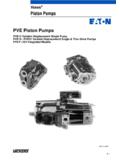
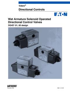
1 February 1996GB-2321AX(C)G2V-6/8, 10 SeriesTypical SectionX(C)G2V-**-1* valveBasic CharacteristicsMax. inlet pressure350 bar .. (5000 psi)Max. reduced pressure330 bar.. (4780 psi)Maximum flow300 L/min (80 USgpm).. Mounting face to ISO 5781(B port high Pressure inlet):X(C)G2V-6AG-06-2-A.. X(C)G2V-8AH-08-2-A.. General DescriptionWhere sections of an hydraulic systemare required to operate at a pressurebelow that of the general system, it isfrequently more convenient to use apressure Reducing valve than to addfurther pump two-stage Pressure reducingvalves allow full flow from inlet to outletport until the reduced Pressure setting isreached, whereupon the outlet flow isclosed off.
2 Reduced Pressure setting ismanually adjustable at the pilot ranges of reduced pressureadjustment are valve response ensures that thereduced outlet Pressure is unaffected byinlet Pressure peaks. Excessive build-upof outlet port Pressure ( caused byflow back from an actuator) is preventedby the small check in the main-stagewhich connects the outlet port to thepilot applications where full reverse flowis required an optional integral checkvalve is available (model types XCG).Models with electrohydraulicproportional control, types KX(C)GV, aredescribed in catalog and BenefitsFClose matching to machinerequirements with choice of fiveadjustment ranges of repeatability and stableperformance results from cartridgedesign of main-stage pump flow losses when usingseveral Valves in parallel, results fromdesign of internal pilot reverse flow from integral checkvalve mounting installed cost and spacerequirement from high power/sizeratios (more than double that of manyconventional designs).
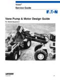
3 Pressure Reducing ValvesVickers Pressure ReliefXCG2V model (integral check valve forfree flow A to B)BAYBAY(F3-)Fluid compatibilityBlank = Anti-wear hydraulic oil (class L-HM), invert emulsion (class L-HFB) or water glycol (class L-HFC)F3 = As above or phosphate ester (class L-HFD)Integral check valve (free reverseflow)C = Integral check valveOmit if not requiredMounting surface, ISO 5781 With B port, high Pressure inlet and Aport, reduced Pressure outlet6 = Size 068 = Size 08X (C) G2V- * * * -1*123456123 Reduced Pressure adjustmentcontrol rangeA = 2 to 35 bar (30 to 500 psi)B = 5 to 70 bar (44 to 1000 psi)C = 5 to 140 bar (44 to 2000 psi)F = 5 to 210 bar (44 to 3000 psi)G = 5 to 330 bar (44 to 4780 psi)Type of manual adjustmentK = Micrometer with keylockM = Micrometer without keylockW = Screw/locknutDesign number, 1* seriesSubject to change.
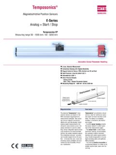
4 Installationdimensions unaltered for designnumbers 10-19 SymbolsXG2V model (no reverse flow check)Model CodeFor Valves with manual adjustment onlyOperating DataData is typical with oil at 22 cSt (106 SUS) and at 50_C (122_F).Maximum pressures:Port B ( Pressure inlet)Port A (reduced Pressure outlet)Port YJ350 bar (5000 psi)See model code position2 bar (30 psi)4 Rated flow rates at p = 12 bar (175 psi):X(C)G2V-6X(C)G2V-8200 L/min (53 USgpm)300 L/min (80 USgpm) Pressure adjustment rangesSee model code position4 Minimum Pressure differential (PB - PA)for effective reduced Pressure control,all models20 bar (300 psi) control drain flow, all modelsat PB 100 bar (1450 psi)at PB 300 bar (4350 psi)1,0 L/min ( USgpm)1,3 L/min ( USgpm)
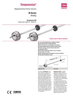
5 Hydraulic fluids and fluid temperaturesSee page 3 Temperature limitsSee page 3 MassSee page 6 Spare parts/service information40630J Back Pressure at this port is additive to the reduced Pressure setting of the Drop050100150200250300bar010002000300040 00psi0010020030020406080L/minUSgpmReduce d pressureFlow rate5015025002481012bar60255075100125150 175psi50100150200250300 L/min020406080 USgpmPressure dropFlow rateABCD1030507013 Pressure UnderrideX(C)G2V-8 examplesFrom port B to A at pressures belowreduced Pressure setting:X(C)G2V-6 Curve A.. X(C)G2V-8 Curve B.. From port A to B through check valve(main stage assumed closed), XCG2 Vmodels only:XCG2V-6 Curve C.. XCG2V-8 Curve D.
6 Hydraulic FluidsAll Valves can be used with: Anti-wear hydraulic oils (class L-HM)Invert emulsions (class L-HFB) Water glycol (class L-HFC) Phosphate ester (class L-HFD), adding F3- prefix at model code .The extreme viscosity range is from 500to 13 cSt (2270 to 70 SUS) but therecommended range is 54 to 13 cSt(245 to 70 SUS).For further information about fluids seecatalog LimitsAmbient:Min. 20_C ( 4_F).. (158_F).. Fluid temperature:Min. 20_C ( 4_F).. Max.*70_C (158_F).. *To obtain optimum service life from both fluid and hydraulic system, 65_C (150_F) normally is the maximum temperature except for water-containing synthetic fluids consult fluidmanufacturer or Vickers representativewhere limits are outside those ofpetroleum the actual temperature range,ensure that viscosities stay within thelimits specified in the Hydraulic Fluids Control RequirementsRecommendations on contaminationcontrol methods and the selection ofproducts to control fluid condition areincluded in Vickers publication 561, Vickers Guide to Systemic ContaminationControl.
7 The book also includesinformation on the Vickers concept of ProActive Maintenance . The followingrecommendations are based on ISOcleanliness levels at 2 mm, 5 mm and 15mm. For products in this catalog therecommended levels are:Up to 210 bar (3050 psi)19/17/14.. Above 210 bar (3050 psi)19/17/14.. Installation Dimensions in mm (inches)3rd angleprojection61,0 ( )CD45,0 ( ) for removal ofprotective cap176,0 ( )HE4 holes 11,0 ( dia)spotfaced to 17,0 ( dia)7,5 ( ) A/FTurn clockwise to increasereduced Pressure setting17,0 ( )A/F98,0( )30,0 ( )16,0 ( )G1/4I (1/4I BSPF)reduced pressuregage portPort B, highpressure inletPort A, reducedpressure outlet120,0 ( )196,0 ( ) fully out25,0( )18,0 ( ) for key removalType K only:FMicrometer Adjustment Options: K or M in Model Code K FeatureTo adjust Pressure setting, insert keyand turn clockwise.
8 Turn micrometerknob clockwise to increase pressuresetting; counter-clockwise to the key is removed, the knob canspin freely without affecting the (C)G2V-642,0( )66,0( )10,0( )89,0( )92,0( )X(C)G2V-840,0( )77,0( )11,0( )104,0( )107,0( )21,0 ( )XCGVM-6-10R SubplatePort Y (see Functional Symbols for usage)Port A (reduced Pressure outlet)Port B (highpressure inlet)Valve locating pin(Not used; recess for O-seal X location)Port Y (see Functional Symbols for usage)Port A (reduced Pressure outlet)Port B (highpressureinlet)Valve locating pin(Not used; recess for O-seal X location)116,0 ( )104,0 ( )80,0 ( )12,0 ( )26,9 ( )43,0 ( )20,0 ( )150,0( )88,0( )24,0( )69,0 ( )126,0( )18,9 ( )Port A uPort B uTapped G1 (1 IBSPF) x 19,0 ( )depth full thread, inundersideR28,0( rad.)
9 7,5 ( dia) x 6,0( ) deep for valve lo-cating pin4 holes, 11,0 ( ) through, 17,5( dia) spotfacePort Y uPort X uTapped G1/4(1/4I BSPF) x12,0 ( )depth fullthread, in un-dersideYXAB4 holes tapped M10 x 16,0 ( ) full thread56,0 ( )YSee Mounting Surfaces section on next page for port on Bottom Face of Valves (See also Mounting Surfaces , page 6. All O-seals supplied).X(C)G2V-6X(C)G2V-8D (min.)F (min.)Q (min.)N (min.)EYJYPYHKLMTSRU(min.) M10 x 16,0 ( )min. depth full thread 4,8 ( dia) 7,5 ( dia) x 6,0 ( ) deep 4,8 ( dia)C(min.)YTolerance on bolt and pin locations "0,1 mm ( ).6 Mounting Surfaces, Based on ISO 5781 Codes:AG-06-2-AAH-08-2-AWhen a subplate is not used a raisedmachined pad must be provided formounting.
10 The pad must be flat within0,01mm/100 mm ( ) andsmooth within 0,8 mm (32 min).Dimensional tolerances are "0,2 mm( ) except where functionsA = Reduced Pressure outlet (also freereverse flow inlet for XCG2V Valves )B = High Pressure inlet (also free reverse flow outlet for XCG2V Valves )X = Not used for X(C)G2V Valves ; can be omitted or pluggedY = Drain portSizeA ,7( )14,7( )61,0( )9,0( )42,9( )9,0( )35,7( )31,8( )21,4( )0823,4( )23,4( )78,0( )8,8( )60,3( )8,8( )49,2( )44,5( )39,7( )SizeLMNPQRSTU0621,4( )7,1( )10,0( )66,7( )10,0( )58,7( )33,3( )7,9( )87,0( )0820,6( )11,1( )10,8( )79,4( )10,8( )73,0( )39,7( )6,4( )101,0( )Installation DataMounting attitude unrestrictedSubplatesFor X(C)G2V-6 Valves see typeXCGVM-6-10R, on page X(C)G2V-8 Valves consult yourVickers Bolts/TorquesFor all models, bolt kit BKXG2V-6.