Transcription of Vickers Pressure Relief Pressure Relief Valves - Eaton
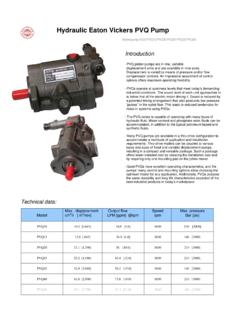
1 Relief ValvesRemote Controls, Relief and Sequence Valves , and Single andMultiple Pressure Solenoid and Air Operated Relief ValvesVickers Pressure Relief2 IntroductionRemote ControlsSmall, easily installed remote pressurecontrol Valves make it possible to controla balanced piston Pressure Relief valvefrom a more convenient and SequenceValvesPressure Relief Valves mount betweenthe pump and valve system to protectagainst overloads. A suitable pilot valvemay be used to vent the balancedpiston Relief valve when the system doesnot require power. This venting unloadsthe pump through the Relief valve at lowpressure, avoiding energy waste andreducing operating sensitive adjustment mechanismallows the setting of the Pressure in fineincrements over a wide range up tothe maximum rating of the Relief Valves at the controlconsole or other remote location, andelimination of separately mountedhydraulic remote controls and relatedconnecting piping, result in lowerinstalled cost.
2 The Valves are availablewith SAE straight threads, NPT threads,or interfaces for manifold or subplatemounting to provide and MultiplePressure Solenoid andAir Operated ValvesThese balanced piston type Valves areused in applications needing anelectrically or pneumatically controlledadjustable Pressure Relief or regulatingvalve to limit the Pressure in a hydrauliccircuit to the desired of ContentsSeries CGE-02/06/10 Remote/Electrically Modulated Controls3.. Series CGR-02 Remote Controls 9.. Series C-175 Remote Control/ Relief Valves11.. Series CG-03 Relief Valves13.. Series C*-03/06/10 Relief /Sequence Valves16.. Series CG-06/10 Relief /Sequence Valves20.. Series CGAM-06/10 Adapter Mounting Plates26.. Series C*5-03/06/10 Pilot Operated Relief Valves28.. Series C*19-06/10 Air Operated Relief Valves38.. Series C*-06/10-DG Bi/Tri- Pressure Relief Valves47.. Series C*-06/10-DG-M-M Bi/Tri- Pressure Relief Valves55.. Application Data61.. 3 Series Model CGE-02/06/10 Remote/Electrically Modulated Controls34512 Model Code12 Model SeriesCGE - Relief valve, manifold orsubplate mounted, remote electricallymodulatedValve Size02 - NFPA-DO3 (ISO-4401-03) interface06 - 60 series (3/4 nominal size)10 - 100 series (1-1/4 nominal size)345 Pressure Rating1 -70 bar (1000 psi)3 -210 bar (3000 psi)High Vent Spring(For CGE-06 & -10 3000 psi pressuremodels only).
3 Omit if not NumberSubject to change. Installationdimensions remain as shown for designnumbers 20 through 29 General InformationThe CGE-02 valve provides the capabilityto modulate system Pressure whenconnected to a Relief or reducing valveor regulating the Pressure setting of apressure compensator variabledisplacement CGE-06/10 provides the capabilityto modulate system Pressure using aremote electrical controller. The pressuresetting of the valve is approximatelyproportional to input current; increasingcurrent provides increasing OperationA manual override adjustment of theCGE-06/10 operates over the full pressurerange and should be set just above themaximum Pressure to be controlledelectrically. For example, the overrideshould be set at 2200 psi when maximumelectrically controlled Pressure is 2000 override adjustment can also beused for complete manual operation ofthe valve during set up and troubleshootingby isolating the pilot head section fromthe manual override section.
4 This is doneby removing an access plug and reversinga button in the pilot section (see fig. 1).Pilot FlowBlockedButton Reversed forManual OperationFigure 1 Electrical Power SupplyVickers power supply EMCS-*-30 isrecommended for controlling this 2 shows the basic diagram(amplifier switch should be in position 1).12 11 10 9 8 7 6 5 4 3 2 1+12V5K 1 WPot115V60 HzValveCoilEMCS-*-30 Power SupplyFigure 2 Tank ConnectionThe tank connection should be pipeddirectly to tank through a surge free lineto minimize back Pressure . If tank lineback Pressure exceeds system pressureby 7 bar (100 psi) a malfunction mayoccur. Any Pressure in the tank line is anadditive when the valve is controlled bythe manually adjusted (non-electrical) Drain ConnectionDrain line must be full size unrestrictedand connected directly to reservoir sothat it terminates below reservoir fluidlevel. No other lines are to be connectedto this drain line. Pressure in this line(taken at the valve) not to exceed 1 bar(15 psi).
5 Graphical SymbolMinimum Pressure Specifications (Zero Current)ModelFlowMinimumPressureL/minUSg pmbarPSICGE-06-1-2* *-2* * * * * 4 Series Model CGE Remote/Electrically Modulated ControlsInstallation DataFilter ScreenThe CGE-02 valve contains a filterscreen in the Pressure port of the valvehead (fig. 3) which may require periodiccleaning, depending on CGE-06/10 Valves contains a filterscreen in the Pressure port of the valvehead (fig. 3) and an additional screen inthe valve body (fig. 4). Both requireperiodic cleaning depending on breaking a circuitconnection, make certainthat power is off andsystem Pressure has been all vertical cylinders, dischargeaccumulators and block any loadwhose movement could generatepressure. Plug all removed units andcap all lines to prevent the entry ofdirt into the remove the filter screen from thevalve head (fig. 3), first shut down themachine and remove the access plug,button, spool and screen. Clean screenand PlugButtonSpoolFilterSpringGuide RodFigure 3To remove the filter screen from the valvebody (fig.)
6 4), first shut down the machineand remove the Relief valve from thepump. Remove the snap ring andscreen. Clean screen and RingSeatFigure 4 RatingsThe CGE Series are rated for amaximum Pressure of 210 bar (3000psi). The table on page 3 lists minimumpressures attainable when the CGE isused with three sizes of system reliefvalves at various system and Flow (see tables on right) Pressure change due to temperature:The maximum Pressure deviation between C (80 F) and C (150 F) is bar (70 psi).Hysteresis:5% of maximum current (without dither-see curves on pages 5 7)3% of maximum current (with dither)Recommended dither: 10 mA (RMS) at 60 HzPower required (maximum): wattsNominal coil resistance: 18 ohmsCurrent required:0-500 mA DC (not polarity sensitive)Response TimeFor response time, see tables that response time will increasewith increasing flows. Also responsetime is dependent on the amount of allvolume in the Pressure side of thecircuit; less oil volume under pressurewill result in faster response input currents of less magnitudewill decrease response time Pressure response will beapproximately 1/4 of response time times shown are typical ofthose experienced with an averagevolume of oil under small volumes of oil undercompression (20-40 cubic inches),response times are 60-80 & Flow RatingsModelMaximumPressurebar (psi)MaximumFlowL/min(USgpm)CGE-02-170 (1000) ( )CGE-02-3210 (3000)CGE-06-1-2*70 (1000)170 (45)CGE-06-3*-2*210 (3000)CGE-10-1-2*70 (1000)380 (100)CGE-10-3*-2*210 (3000)
7 Minimum Controllable FlowsModelL/minUSgpmCGE-06-* * input mAFlowPressure IncreaseResponse Time-msResponse Time, typicalL/min USgpmbarPSICGE-06-1-2*CGE-06-3*-2*CGE-10 -1-2*CGE-10-3*-2*0-5007618920505-7010-21 05-7010-21075-1000150-300075-1000150-300 02502904002405 Performance CurvesSYSTEM Pressure barSYSTEM Pressure psiFLOW USgpmFLOW l/minSYSTEM Pressure barSYSTEM Pressure barSYSTEM Pressure psiSYSTEM Pressure psiFLOW l/minInput Current (mA)FLOW USgpmCGE-06-3-2* Pressure vs System Flow21014070021014070014,07,003000200010 00300020001000100 Zero CurrentValve Vented Flow 76 L/min (20 USgpm) Pressure vs Current010020030040050001020304050010203 040500 CGE-02-3-20 SYSTEM Pressure barSYSTEM Pressure psi250200150100500mA1002003004005006004 l/min ( USgpm)3 l/min ( USgpm)2 l/min ( USgpm)1 l/min ( USgpm)Constant Input Flow300015005003500250020001000 SYSTEM Pressure barSYSTEM Pressure psiFLOW USgpmSYSTEM Pressure barSYSTEM Pressure barSYSTEM Pressure psiSYSTEM Pressure psiFLOW l/minInput Current (mA)FLOW USgpmCGE-06-3V-2*21014070021014070028,01 4,00300020001000300020001000400200010020 030040050001020304050010203040500 Minimum Pressure vs System FlowFLOW l/min40801201602004080120160040801201604 080120160 Valve VentedZero Current6 Performance CurvesFLOW USgpmFLOW l/minFLOW l/minInput Current (mA)FLOW USgpmSYSTEM Pressure psiSYSTEM Pressure psiSYSTEM Pressure psiSYSTEM Pressure barSYSTEM Pressure barSYSTEM Pressure barCGE-06-1-2* Pressure vs System FlowMinimum Pressure vs System Flow21014070021014070014,07,003000200010 00300020001000200100 Zero CurrentValve Vented0100200300400500102030405001020304 0500 Flow 76 L/min (20 USgpm)
8 FLOW USgpmFLOW l/minFLOW l/minSYSTEM Pressure psiSYSTEM Pressure psiSYSTEM Pressure psiSYSTEM Pressure barSYSTEM Pressure barSYSTEM Pressure barCGE-10-3-2*21014070021014070014,07,00 300020001000300020001000200100 Zero CurrentValve VentedInput Current (mA)204060801000204060801000 FLOW USgpm40801201604080120160408012016040801 20160 Pressure vs Current Flow 189 L/min (50 USgpm)01002003004005007 SYSTEM Pressure barSYSTEM Pressure psiFLOW USgpmFLOW l/minSYSTEM Pressure barSYSTEM Pressure barSYSTEM Pressure psiSYSTEM Pressure psiFLOW l/minInput Current (mA)FLOW USgpmFLOW USgpmFLOW l/minFLOW l/minInput Current (mA)FLOW USgpmSYSTEM Pressure psiSYSTEM Pressure psiSYSTEM Pressure psiSYSTEM Pressure barSYSTEM Pressure barSYSTEM Pressure bar Flow 189 L/min (50 USgpm) Pressure vs CurrentPressure vs System FlowMinimum Pressure vs System Flow2101407002101407007035028,014,0014,0 7,00300020001000300020001000100050040020 0200100 Zero CurrentZero CurrentValve VentedValve Vented0100200300400500010020030040050020 4060801000 CGE-10-3V-2*CGE-10-1-2*70350100050020406 0801000204060801000204060801000408012016 04080120160408012016040801201608 Series Model CGE Remote/Electrically Modulated ControlsInstallation Dimensions 37,4 ( ) 42,5 ( ) 92,0 ( ) 81,0 ( ) 151,0 ( ) 17,6 ( ) 65,1 ( ) 89,0 ( )CGE-02mm (inch) 6,4 ( )CGE-06/10-**-2*QRFKCLJMSGH 89,0 ( )T 81,0 ( ) 92,0 ( )EDP 62,0 ( ) 57,2 ( )mm (inch) A Dia.
9 Thru, B Counter Bore, C Depth 4-Holes for MountingModelABCDEFGHJKLMNM odelABCDEFGHJKLMNCGE-0616,6( )24,6( )47,8( )53,4( )106,4( )103,1( )220,5( )244,4( )165,0( )38,9( )158,6( )127,0( )71,4( )CGE-1019,8( )29,3( )63,5( )66,8( )133,4( )109,5( )231,7( )255,5( )170,5( )42,9( )164,1( )138,2( )85,9( ) ,1( )54,1( )173,0( )192,8( )13,3( )102246,0( )59,6( )184,2( )204,2( )26,9( )13299 Series CGR-02 Remote Controls34561212 SealsF3 For mineral oil and fire resistantfluidsBlank Omit if not requiredModel SeriesC Relief valveG Subplate mountedR Remote control34 Valve Size02 6,35 mm (1/4 in) nominal sizeMaximum Adjustable PressureB 70 bar (1000 psi)C 140 bar (2000 psi)F 210 bar (3000 psi)56 Adjusting KnobK Optional adjusting knobinstalledBlank Omit if not requiredDesign NumberSubject to change. Installation dimensionssame for designs 30 through CodeGeneral InformationTypical application is as a remotecontrol device for balanced piston typerelief Valves . The CGR-02 is notintended for use as a Relief valve byitself.
10 The valve is normally used toprovide adjustment of system pressurefrom a convenient or remote RangeThe available Pressure ranges for thisvalve are from 4,5 to 70 bar (65 to 1000psi), from 4,5 to 140 bar (65 to 2000psi), and from 4,5 to 210 bar (65 to 3000psi). Therefore, the main system reliefvalve being controlled by the CGR-02should be selected according to themaximum Pressure required in thesystem. Check the model code for themain system Relief AdjustmentPressure can be adjusted by looseninga jam nut and turning an adjustmentscrew or optional adjustment clockwise increases Pressure ,and turning counterclockwise decreasespressure. The maximum Pressure thatcan be attained by turning the adjustingscrew is set at the factory to the valuespecified in the model SymbolRatingsThe CGR-02 is rated for a maximumpressure of 210 bar (3000 psi). The following table lists minimum pressuresattainable when the CGR-02 is usedwith five sizes of system Relief valvesat various system l/min (USgpm) Through Main System Relief Valve19 (5)38 (10)78 (20)170 (45)284 (75)379 (100)568 (150)758 (200)947 (250)ModelMinimum Pressure bar (psi)CS*-03-*-504,7 (68)5,0 (73)5,9 (86)9,5 (138) CS*-03-*V-507,4 (108)8,4 (122)10,0 (145)12,8 (186) C**-06-*-504,7 (68)5,0 (73)5,9 (86)9,5 (138) C**-06-*V-507,4 (108)8,4 (122)10,0 (145)12,8 (186) C**-10-*-30 4,8 (69)4,9 (71)5,5 (80)7,6 (110)12,0 (174) C**-10-*B-30 10,1 (146)10,7 (155)11,9 (172)12,6 (182)13,5 (196) CF-16-*-10 3,6 (52)3,9 (56)4,3 (62)4,6 (66)4,7 (68)4,8 (70) CF-16-*V-10 13,2 (192)14,1 (204)15,5 (225)16,8 (244)17,1 (248)17,6 (255) CF-24-*-10 15,5 (225)18,6 (270)22,1 (320)31,0 (450)40,7 (590)48,3 (700)CF-24-*V-10 51,7 (750)56,6 (820)59,3 (860)61,4 (890)62,4 (905)63,1 (915)10 Series CGR-02 Remote Controls47,5( )53,9( ) 22,3( )93,7( )