Transcription of VICKERS Proportional Valves Proportional Pressure …
1 KCG-6 Valve with Type U Coil ConnectionThis product has been designed and tested to meet specific standards outlined in the European ElectromagneticCompatibility Directive (EMC) 89/336/EEC, amended by 91/263/EEC, 92/31/EEC and 93/68/EEC, article 5. Forinstructions on installation requirements to achieve effective protection levels, see this leaflet, the InstallationWiring Practices for VICKERS Electronic Products leaflet 2468 and leaflet 02-123931A which is packed with everyKA valve. Wiring practices relevant to this Directive are indicated by Electromagnetic Compatibility (EMC).GB-2324 DRevised 10/97K(A)CG-6/8, 1* SeriesBasic CharacteristicsMax. pressure350 bar (5000 psi).. Max. flow rate400 L/min (106 USgpm).
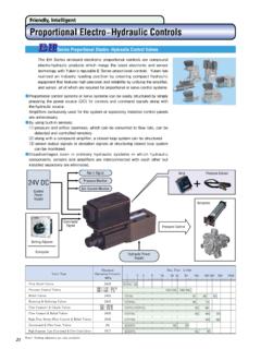
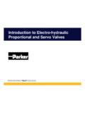
2 Mounting face to ISO 6264: For K(A)CG-6AR-06-2-A.. For K(A)CG-8AS-08-2-A.. General DescriptionThese two-stage Pressure relief Valves (based on VICKERS type CG2V valvesfeatured in catalog 2323) offer extensiveapplication possibilities through theirability to control the Pressure setting inproportion to an applied electrical input(up to a Pressure limit which is manuallyadjustable and lockable).Two model types are availableKCG-6/8 The valve responds to variations ofcurrent input to its solenoid, for whichseparate VICKERS drive amplifiers, withPWM output stage and output currentcontrol, are Proportional pilot control stage is aVickers type KCG-3 valve, described incatalog addition of an integral amplifierallows the Pressure to be controlled froma 0 to +10V, or 0 to 10V commandsignal range.
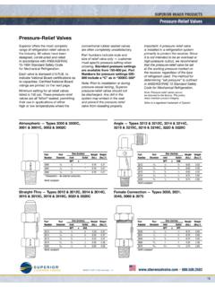
3 The amplifier is mounted ina robust metal housing and electricalconnections are via an industry standard7-pin plug. Factory-set adjustmentsensure high reproducibility and Benefits With or without integrated electronics. Remote electrical Proportional controlof Pressure from a choice of fivepressure ranges per valve size. Excellent repeatability and stableperformance results from cartridgedesign of mainstage elements. Low installed cost and spacerequirement from high power/sizeratios (more than double that of manyconventional designs). Proportional Pressure Relief ValvesVICKERS Proportional ValvesPTTPXKCG-6/8 with manual and electricalpilots internally drained to port T: Model code = BlankKCG-6/8 with manual and electricalpilots drained to side drain port : Model code = 15 PTTPXSide drainport u Tapped port on side of pilot with manual pilot internallydrained to port T.
4 Electrical pilotdrained to side drain port : Model code = 3 Side drainport uPTTPX5 Tapped port on side of pilot with manual and electricalpilots internally drained to port T: Model code = BlankKACG-6/8 with manual and electricalpilots drained to side drain port : Model code = 15 PTTPXSide drainport u Tapped port on side of pilot with manual pilotinternally drained to port T; electricalpilot drained to side drain port : Model code = 3 Side drainport uPTTPX5 Tapped port on side of pilot plug7-pin plug7-pin plug 2 Functional SymbolsPilot drain optionsSee also Functional Symbols CodeDrain routing:Manual Electricalpilot stagepilot stageBlankPort TPort T1 Side portSide port3 Port TSide portStandard featuresZ-M = For KCG-6/8 and KACG-6/8 Coil connection type (KCGonly)U= ISO 4400 (DIN43650) interface FW = Flying-leads in wiring box tapped 1/2 NPTFTW= As FW plus terminal stripFJ = Flying-leads in wiring box tapped M20 FTJ = As FJ plus terminal stripP= Plug-in coil (type H only)Use with EN46 Female connector to be suppliedby (KACG only)PD7 = 7 pin connector with Warning note regarding CEcompliance on pageNO TAG1(F3-)KCG- * * **-1*2912--*- Z-M- **6-**(-EN46)13 Fluid compatibilityBlank = Antiwear hydraulic oil (class L-HM)
5 F3 = As above or phosphate ester (class L-HFD)Valve typeKC = Proportional Pressure reliefKAC = Proportional Pressure relief with integral amplifierMounting typeG = Subplate mountedMounting surface, ISO 62646 = AR-06-2-A8 = AS-08-2-AType of manual adjustmentK = Micrometer with keylockM = Micrometer without keylockW = Screw/locknutPressure adjustment controlrange(All coils except type HJ, see position , footnote )40 = 6 - 40 bar (87 - 580 psi)100 = 7,75 - 100 bar (112 - 1450 psi)160 = 8,5 - 160 bar (125 - 2300 psi)250 = 8,5 - 250 bar (125 - 3600 psi)350 = 9,0 - 350 bar (130 - 5000 psi)123 Coil ratingCode = amps x ohms G1 = 3,5 x 1,65GP1 = 3,0 x 2,0H1 = 1,6 x 7,3 HA1 = 0,94 x 22HJ1 = 1,0 x 14,25 HL1 = 0,80 x 29 Resistance at 20 C (68 F).
6 KACG Valves must have H1 coilslFor Valves replacing CGEV models. This lower power coil is limited tothe following maximum controlledpressures. Valves supplied with type HJ coils will be stamped with theapplicable maximum codeMax. pressurepositionwith HJ coil4035 bar (500 psi)10085 bar (1100 psi)160140 bar (2000 psi)250210 bar (3000 psi)350315 bar (4500 psi)Design number, 1* seriesSubject to change. Installationdimensions unaltered for designnumbers 10 to 19 featuresEN46 used with P-type coil connectionand Uniplug connector. Omit if not in brackets () may be omitted. All other features must be (F3-)KACG- * * **-1*3278--*- Z-M- PD76-H14589101211101112133457811 Models requiring separate amplifiersModels with integral amplifier 3 Model CodeOperating Data 4 Standard test conditions are with antiwear hydraulic oil at 36 cSt (168 SUS) and 50 C (122 F)Maximum pressures:Ports P and X Port T in K(A)CG-*-**-Z- valvesPort T in K(A)CG-*-**-1/3-Z- valvesSide drain port sBack Pressure at these ports additive to the Pressure setting of the bar (5000 psi)2 bar (30 psi)350 bar (5000 psi)2 bar (30 psi)Rated flow at Dp = 6 bar (87 psi).
7 K(A)CG-6K(A)CG-8200 L/min ( USgpm)400 L/min ( USgpm)Vent flow with valve at rated flow See Venting , page L/min ( USgpm)Pilot control drain flow, when valve is limiting systempressure, flow P to T occurring:K(A)CG-6K(A)CG-81,3 L/min ( USgpm)2,0 L/min ( USgpm)Coil or amplifier rating:KCG modelsKACG modelsSee in Model Code 24V x 40W max. (22 to 36V including 10% pk. to pk. max. ripple)11 Command signal ranges, KACG models0 to +10V DC, or 0 to 10V DCDither, KACG modelsFactory set, not user adjustableMonitor point signal, KACG models0,5V per amp. solenoid currentPower stage PWM, KACG models2kHz nominal7-pin plug connections, KACG models:ABCDEFGP ower supply +vePower 0 VSignal 0V+ve voltage command signal ve voltage cpommand signalMonitor outputProtective groundElectro-magnetic compatibility (EMC)KACG models only: Emission (10V/m) Immunity (10V/m)EN 50081-2EN 50082-2 Pressure gain, KACG modelsFactory setting - Maximum with 10V command signal.
8 User adjustment - 30 to 120% of factory setting. Note that altering this setting will affect valve to graphPressure override when relieving and when off-loadSee graphsHysteresis KCG models KACG models<5% (with 100 mA dither)<6% (with factory-set dither)Linearity, between 10% and 100% of rated Pressure :K(A)CG-6 models at 100 L/min (26 USgpm)K(A)CG-8 models at 200 L/min (52 USgpm)<6%<6%Operating Data 5 Repeatability<1,3% of rated pressureProtection, Electrical (KACG models)Reverse-polarity protectedMass (weight) KCG-6 KACG-6 KCG-8 KACG-84,9 kg ( lb)5,3 kg ( lb)5,8 kg ( lb)6,2 kg ( lb)Supporting products:Amplifiers for KCG Valves with H type coils only:EHH-AMP-724-C/D-10 (Uniplug)EHH-AMP-7*2 series (power plug)EEA-PAM-513-A-14 (1 adjustable ramp)EEA-PAM-513-A-3* (2 adjustable ramps)Auxilliary electronic modules (Din-rail mounting) forKACG models:EHA CON 201 A 2* signal converterEHD DSG 201 A 1* command signal generatorEHA RMP 201 A 2* ramp generatorEHA PID 201 A 2* PID controllerEHA PSU 201 A 1* power supplyISO 4400 (DIN 43650) electrical connector:Black, marked B Gray, marked A Subplates, size 03 Mounting bolts Note.
9 If not using VICKERS recommended bolt kits, boltsmust be to ISO 898 grade or catalog 2367 See catalogs 2114, 2115 and 2282 See catalog 2137 See catalog 2464 See catalog 2410 BSee catalog 2470 See catalog 2410 BSee catalog 2427 See catalog 2410 BPart number 710775 Part number 710776 See catalog 2425 See catalog 2314 AInstallation and start-up (commissioning):Installation and start-up (commissioning) guideMounting attitudeML-B-9133B (Multi-lingual English, German, French and Italian),shipped with each product and also available separately restriction, provided that the valve is kept full of fluid throughport procedureValves, subplates, bolt kits and VICKERS amplifiers should beordered by full model code designation.
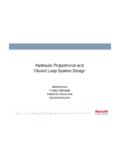
10 Order ISO (DIN)electrical connectors by part DataTypical with oil at 36 cSt (168 SUS) and at 50 C (122 F)050100150200250300350bar01000200030004 0005000psiFlow rateKCG-8 KCG-60010020040020406080L/minUSgpm001020 3040L/minUSgpm40801201603001002005012345 6789 Pressure024810bar60255075100125psi100200 300L/min020406080 USgpmFlow ratePressure Override Off-LoadGraphs show the minimum pressuresobtainable:a) With 0 mA current to the solenoid coilb) When the valve is vented (see following explanation).Venting When the vent port X (or alternativevent port in the valve body) isconnected to the reservoir via asuitable 2-way pilot valve, themainstage of the relief valve opens toallow full flow from P to T at lowpressure drop.