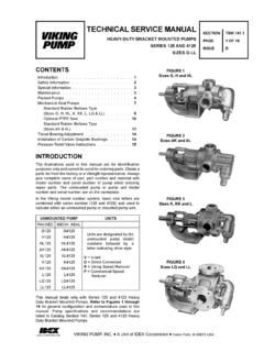
Transcription of Viking Pump with Motor and Gear Reduction Drive
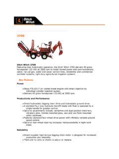
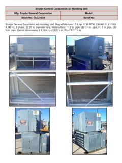
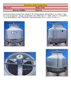
1 Viking Pump with Motor and gear Reduction Drive Mfg: Viking Model: Stock No. Serial No. Viking Pump with Motor and gear Reduction Drive . Motor : Ajax Electric Motors. Type DFT100L4. 23/450 volt, 60 Hz, amps, 5 hp, 3 phase. Pump runs 150 gpm @520 rpm. Works best pumping lubricating fluids, not water, as the rotary gears are cast iron. Cost new $ 2,100. CONTENTS Special Information 2 Maintenance 2 Packed pumps 3 Mechanical Seal pumps Standard Rubber Bellows Type (Sizes G, H, HL, K, KK, L, LQ & LL) 6 Optional Teflon Seal 9 Standard Rubber Bellows Type (Sizes AK&AL) 11 Thrust Bearing Adjustment 13 Installation of Carbon Graphite Bushings 13 Pressure Relief Valve Instructions 14 INTRODUCTION The illustrations used in this manual are for identification purposes only and cannot be used for ordering parts.
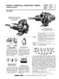
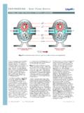
2 Obtain a parts list from the factory or a Viking representative. Always give complete name of part, part number and material with model number and serial number of pump when ordering repair parts. The unmounted pump or pump unit model number and serial number are on the nameplate. In the Viking model number system, basic size letters are combined with series number (125 and 4125) indicating both unmounted or mounted pump unit. This manual deals only with Series 125 and 4125 HeavyDuty Bracket Mounted pumps . Refer to Figures 1 thru 19 for general configuration and nomenclature used in this manual. Pump specifications and recommendations are listed in Catalog Section 141, Series 125 and 4125 HeavyDuty Bracket Mounted pumps .
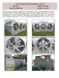
3 Viking PUMP INC. A Unit of IDEX Corporation UNMOUNTED PUMP UNITS PACKED MECH. SEAL G125 G4125 H125 H4125 HL125 HL4125 AK125 AK4125 Units are designed by the unmounted pump model numbers followed by a letter indicating Drive style. AL125 AL4125 K125 K4125 V=V-belt KK125 KK4125 D=Direct Connected L125 L4125 R= Viking Speed Reducer LQ125 LQ4125 P=Commercial Speed Reducer LL125 LL4125 FIGURE 4 Sizes LQ and LL FIGURE 3 Sizes K. KK and LL FIGURE 2 Sizes AK and AL FIGURE 1 Sizes G, H and HL TECHNICAL SERVICE MANUAL HEAVY-DUTY BRACKET MOUNTED pumps SERIES 125 and 4125 SIZES G-LL SECTION TSM 1 ISSUE C DANGER BEFORE OPENING ANY Viking PUMP LIQUID CHAMBER (PUMPING CHAMBER, RESERVOIR, RELIEF VALVE ADJUSTING CAP FITTING ETC.)
4 BE SURE: 1. THAT ANY PRESSURE IN CHAMBER HAS BEEN COMPLETELY VENTED THROUGH SUCTION OR DISCHARGE LINES OR OTHER APPROPRIATE OPENINGS OR CONNECTIONS. 2. THAT THE DRIVING MEANS ( Motor , TURBINE, ENGINE, ETC.) HAS BEEN LOCKED OUT OR MADE NON-OPERATIONAL SO THAT IT CANNOT BE STARTED WHILE WORK IS BEING DONE ON PUMP. 3. THAT YOU KNOW WHAT LIQUID THE PUMP HAS BEEN HANDLING AND THE PRECAUTIONS NECESSARY TO SAFELY HANDLE THE LIQUID. OBTAIN A MATERIAL SAFETY DATA SHEET (MSDS) FOR THE LIQUID TO BE SURE THESE PRECAUTIONS ARE UNDERSTOOD. FAILURE TO FOLLOW ABOVE LISTED PRECAUTIONARY MEASURES MAY RESULT IN SERIOUS INJURY OR DEATH.
5 SPECIAL INFORMATION ROTATION: Viking pumps operate equally well in a clockwise or counterclockwise rotation. Shaft rotation determines which port is suction and which is discharge. Port in area where pumping elements ( gear teeth) come out of mesh is suction port. PRESSURE RELIEF VALVES: 1. Viking pumps are positive displacement pumps and must be provided with some sort of pressure protection. This may be a relief valve mounted directly on the pump, an inline pressure relief valve, a torque limiting device or a rupture disk. 2. There are relief valve options available on those pump models designed to accept a relief valve. Options may include a return to tank relief valve and a jacketed relief valve.
6 pumps equipped with a jacketed head plate are generally not available with a relief valve. 3. If pump rotation is reversed during operation, pressure protection must be provided on both sides of pump. 4. Relief valve adjusting screw cap must always point towards suction side of pump. If pump rotation is reversed, remove pressure relief valve and turn end for end. Refer to Figures 1, 2, 3 and 4. 5. Pressure relief valves cannot be used to control pump flow or regulate discharge pressure. For additional information on pressure relief valves, refer toTechnical Service Manual TSM000 and Engineering Service Bulletin ESB-31. SPECIAL INFORMATION SPECIAL MECHANICAL SEALS can be installed either next to rotor hub or in an altered stuffing box.
7 Extra care must be taken in repair of pumps with mechanical seals. Read and follow all special information supplied with pump. MAINTENANCE Series 125 and 4125 pumps are designed for long, trouble-free service life under a wide variety of application conditions with a minimum of maintenance. The points listed below will help provide long service life. LUBRICATION: External lubrication must be applied slowly with a hand gun to all lubrication fittings every 500 hours of operation with multi-purpose grease, NLGI #2. Do not over-grease. Applications involving very high or low temperatures will require other types of lubrication. Refer to Engineering Service Bulletin ESB-515. Consult factory with specific lubrication questions.
8 PACKING ADJUSTMENT: New packed pumps require initial packing adjustment to control leakage as packing runs in . Make initial adjustments carefully and do not over-tighten packing gland. After initial adjustment, inspection will reveal need for packing gland adjustment or packing replacement. Refer to instructions under Disassembly, page 4, and Assembly, page 4, regarding repacking pump. CLEANING PUMP: Keep pump as clean as possible. This will facilitate inspection, adjustment and repair work and help prevent overlooking a dirt covered grease fitting. STORAGE: If pump is to be stored, or not used for six months or more, pump must be drained and a light coat of non-detergent SAE 30 weight oil must be applied to all internal pump parts.
9 Lubricate fittings and apply grease to pump shaft extension. Viking suggests rotating pump shaft by hand one complete revolution every 30 days to circulate the oil. SUGGESTED REPAIR TOOLS: The following tools must be available to properly repair Series 125 and 4125 pumps . These tools are in addition to standard mechanics tools such as open end wrenches, pliers, screw drivers, etc. Most of the items can be obtained from an industrial supply house. 1. Soft Headed hammer 2. AlIen wrenches (some mechanical seals and set collars) 3. Packing hooks, flexible (packed pumps ) Small for inch and inch cross section packing Large for inch and up cross section packing 4. Mechanical seal installation sleeve Viking Part No. 2-751-001-900 for inch seal; G4125 Viking Part No.
10 2-751-002-900 for inch seal; H &HL4125 Viking Part No. 2-751-003-900 for inch seal; AK - LL4 125 5. Bearing locknut spanner wrench (Source: #471 J. H. Williams & Co. or equal) 6. Spanner wrench, adjustable pin type for use on double end caps (Source: #482 J. H. Williams & Co. or equal) 7. Brass bar 8. Arbor press 2 3 ITEM NAME OF PART ITEM NAME OF PART ITEM NAME OF PART ITEM NAME OF PART 1 Locknut 10 Packing Gland 19 Bracket Gasket 28 Gasket for Jacketed Head Plate 2 Lockwasher (Not G) 11 Packing Gland Nut 20 Casing 29 Jacketed Head Plate 3 End Cap (Outer) 12 Packing Gland Capscrew 21 Pipe Plug 30 Capscrew for Head 4 Lip Seal for End Cap 13 Packing 22 Rotor and Shaft 31 Relief Valve Gasket 5 Bearing Spacer Collar (Outer) 14 Packing Retaining Washer 23 Idler and Bushing 32 Capscrew for Valve 6 Ball Bearing 15 Bracket Bushing 24 Idler Bushing 33 Internal Relief Valve 7 Bearing Spacer Collar (Inner) 16 Grease Fitting 25 Head Gasket 8 Ring, Half Round (Not G,H,HL) 17 Bracket and Bushing 26 Idler Pin 9 End Cap (Inner)

![BorgWarner eGearDrive(for customer) [兼容模式]](/cache/preview/a/d/d/9/8/4/2/5/thumb-add9842573e443c2740dc638242b6cd8.jpg)