Transcription of VIRTUAL H.264 8/16 CH DVR USER GUIDE - Surveillance
1 VIRTUAL 8/ 16 ch dvr user guide 1 TABLE OF CONTENTS 1. Features .. 5 2. Hardware Overview .. 6 2-1. Hardware .. 6 2-2. Front Panel .. 8 2-3. Back Panel .. 9 2-4. Remote Controller .. 9 3. System Setup .. 10 3-1. Setup Main Screen .. 10 3-2. Setup Live Mode .. 12 3-3. Setup Recording Mode .. 13 3-3-1. Motion Zones .. 14 3-3-2. Recording Schedule .. 14 3-4. Setup Device Mode .. 15 3-4-1. ALARM-OUT .. 16 3-4-2. PTZ Setup .. 16 3-5. Setup System Mode .. 17 3-6. Setup Security Mode .. 19 3-7. Setup Network Mode .. 19 3-7-1. Ports .. 20 3-7-2. Network types .. 21 3-7-2-1. LAN .. 21 3-7-2-1. DHCP .. 21 3-7-2-1. ADSL (PPPOE) .. 21 3-7-3. SEND E-MAIL .. 21 3-8. Setup - Storage Mode .. 22 3-9. Save Setup .. 22 4. Live & Search .. 23 4-1. Live Window.
2 23 4-2. Search Window .. 24 4-2-1. TIME LINE SEARCH .. 24 4-2-2. EVENT Search.. 25 4-2-3. GO TO SPECIFIC TIME .. 26 4-2-4. GO FIRST TIME .. 26 4-2-5. GO LAST TIME .. 26 4-2-6. LOG .. 27 4-2-7. ARCHIVE .. 27 DATE: 2009/03/01 VER VIRTUAL 8/ 16 ch dvr user guide 24-3. Play mode .. 28 5. Archiving And Backup .. 29 5-1. Capturing Still Images or video .. 29 5-1-1. Live Mode .. 29 5-1-2. Playbak Mode .. 29 5-2. Backp Still Images or video from Archive List .. 30 5-3. Backup video Playback .. 31 5-3-1. Playback Backup video in AVI Format .. 31 5-3-2. Playback Backup video in Exclusive (NaFs) Format .. 31 6. Upgrading Firmware .. 32 7. Network Remote Viewer .. 33 7-1. Overview .. 33 7-2. Minimum PC Requirements .. 33 7-3. Program Installation .. 33 7-4. Live viewer.
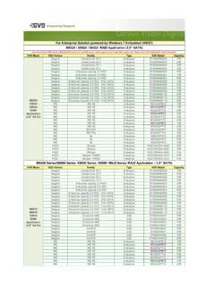
3 34 7-5. Search and Playback Viewer .. 36 7-5-1. Backup .. 37 7-6. PC System Configuration .. 37 7-6-1. General .. 37 7-6-2. Site .. 38 7-6-3. Event .. 38 7-6-4. Record .. 39 7-6-5. Disk .. 39 8. Network IE Browser Viewer .. 40 8-1. Download Web Brower Viewer and Connection .. 40 8-2. Main Features .. 41 8-2-1. Live .. 41 8-2-2. Search and Playback .. 42 APPENDIX .. 43 1. Registering DDNS in 43 2. DDNS Settings .. 47 Remote Software or IE Browser.. 48 APPENDIX 2 HDD Compatiable 50 VIRTUAL 8/ 16 ch dvr user guide 3 SPECIFICATIONS Item 8/16 Channel, 120 fps(or 100fps) video Input Channel, Input Level8/16 CH, Composite , 75 Ohm Signal Format NTSC/PAL(Auto detection) Output 1 CH Composite Output/15pin D-Sub VGA Output Audio Input / Output 4 Line In / 1 Line Out Alarm Sensor Input 4 (NC/NO Selectable) Alarm Output 1 ( By Alarm, Motion, video Loss) Recording Compression VIRTUAL Multi Operation Triplex (Playback/Record/Network) ResolutionNTSC 120fps(CIF) / 60 fps(Half-D1) / 30 fps(D1) PAL 100fps(CIF) / 50 fps(Half-D1) / 25 fps(D1)
4 Recording Quality Grade Network/Standard/High/Superior/Ultra Recording Mode Continuous / Schedule / Motion/ Sensor/ Manual Motion Detection Motion detection setup by Grid Display Speed Real Time Display(NTSC/PAL) Playback Search Mode Event, Archive, Log, Time Line Storage Internal HDD S-ATA (Up to 1TB) Backup USB flash stickJPEG & AVI & DVR Network Moving picture & Still Image Serial port Camera Control 1 RS-485 Network Dynamic IP Support Ye s Network Interface 10/100 base-T Ethernet (RJ-45) Client S/W Functions Live, Search, Backup General Power Source DC 12V 5A Unit Weight Dimension (W x H x D) 435(W) x 335(D) x 54(H) Operation Temperature During operation: 5 C - 40 C During storage: -10 C - +50 C Operation Humidity 0 - 90% VIRTUAL 8/ 16 ch dvr user guide 4 Warnings Installation and servicing should be performed by qualified and experienced personnel only.
5 DVR should always remain OFF during any installation process Product Components The package contains the main unit and its components as specified below. When you purchase the unit, please check to ensure the components specified below are included DVR Set X1 Client Software CD X1 Remote Control X1 (AAA x 2EA) X1 user Manual X1 Power Adaptor X1 Power Cord X1 VIRTUAL 8/ 16 ch dvr user guide 51. Features 8/16 channels real-time live display and 8/16 channels simultaneous playback. VIRTUAL - Unbeatable recording picture quality and compression ratio has been tuned for years. It best fits for minimizing recording space and networking speed. TRIPLEX - Simultaneous Recording, Playback, and Networking NaFS (File System developed) - Designed & developed for preventing loss and broke of recording data by any power failure.
6 Multiplexing operation Reliability - Real Time Operating System and simplified hardware as well as watchdog timer ensure the reliability. Individual channel recording and playback with different frame rate. High-quality live and playback resolution. Multi-site management - Supported by CMS application. Network features - Remote Live, Playback, and Backup. Network via LAN, DHCP, DDNS,ADSL (Dynamic and Static IP address). user -friendly setup menu with graphic user interface. Easy to schedule a complicated weekly recording plan. The OSD icons on screen provide various helpful and well-explained information. Motion detection Grid 15x12 motion zone per camera is provided. USB ports for JPEG, data backup and software upgrade using USB flash memory stick.
7 Still image capture and review as JPEG format. Easy operating with the buttons on the front and the remote controller. user verification by password certification. video loss detection. Backup - Still-images or AVI data into USB flash memory stick and Network. Multi-Languages - user can easily select language from Setup menu. VIRTUAL 8/ 16 ch dvr user guide 62. Hardware Overview 2-1 Hardware USB PORT Front Panel 8ch DVR BASE 16ch DVR BASE 16ch Audio Cable VIRTUAL 8/ 16 ch dvr user guide 7 Please remove top cover of the DVR (show as picture above) and install one of the HDD below: Size Buffer HITACHI 160 GB~1TB 8 MB~16MB MAXTOR 160 GB~300GB 2 MB~16MB WesternDigital 200 GB~1TB 8 MB~16MB Seagate 80GB~1TB 2MB~32MB Compatible HDD List IMPORTANT: DO NOT USE THE FOLLOWING HDD: 1.
8 MAXTOR 160GB (MODEL NUMBER: 6L160PO) HDD 2. WESTERN DIGITAL 320GB HDD 3. PLEASE REFER TO APPENDIX 2 FOR DETAIL HDD COMPATIBLE LIST. VIRTUAL 8/ 16 ch dvr user guide 82-2. Front Panel Front Panel buttons Name Description NUMBER(1~0) Select channel with number button (use +10 button for 16ch DVR) SEQ Auto sequencing of channels in full screen mode. (Toggle) PTZ Enter PTZ mode SETUP Enter SYSTEM SETUP menu. SEARCH Enter Search >Event search /Time line search /Log /Archive search BACKUP Archiving in live or playback mode. Live mode: Backup live picture only Playback mode: Backup picture and video ee Rewind the footage at 1x, 2x, and 4x speed in playback mode.
9 E Jump/Step backward. In playback mode, the playback position moves 60 seconds backward. f Jump/Step forward In playback mode, the playback position moves 60 seconds forward. ff Fast forward the footage at 1x, 2x, and 4x speeds in playback mode REC Start and stop recording manually. UP Scroll up in the system menu or select camera 1 in live mode. It can also be used as number 1 when entering password. RIGHT Move right or change values in system menu or select camera 2 in live mode. It can also be used as number 2 when entering password. DOWN Scroll down in the system menu or select camera 3 in live mode. It can also be used as number 3 when entering password. LEFT Move left or change values in system menu or select camera 4 in live mode. It can also be used as number 4 when entering password.
10 Enter Select full screen or quad view in live display mode. ESC Return or cancel command Front LED and Port Name Description LCD Solid light when DVR is power on. HDD Solid light when DVR is accessing hard disk. VIRTUAL 8/ 16 ch dvr user guide 92-3. Rear Panel Table Rear Panel Connections Label Operation video IN 8 /16 connectors for video input. Connect camera output to video -in (NTSC/PAL) video OUT 1 connector for video output. VGA Connector for VGA monitor AUDIO Audio 1~4:AUDIO IN/ADUIO OUT(16ch use DSUB-9 for audio input and output) SENSOR IN Connection for sensor device.