Transcription of VLT® Micro Drive FC 51 - Danfoss
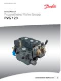
1 Small, powerful and built to last Save panel space and reduce installation costs Selection Guide | VLT Micro %motor torque for upto 1 minute enables you to use a smaller Drive without sacrificing efficiencyReady Steady Go! Connect motor and power cables, turn the control knob, and watch the motor speed changeRoHS compliantThe product complies to RoHS directive 2011/65/EU134667892101112131112131451 Well protected IP 20 enclosure No forced air flow through electronics2 IP 20 even without terminal cover3 High quality capacitors4 RFI Filter5 DC-link access6 Hot pluggable LCP7 LCD display8 Potentiometer9 RS 485 pluggable10 Customer relay screw terminals Wire inlet from the bottom11 Safety earth min. 4 mm2 accessible from front12 I/O terminals13 Mains screw terminals14 Motor screw terminals2 Danfoss Drives VLT qualityVLT Micro Drive is a genuine VLT frequency converter with unsurpassed reliability, user-friendliness, condensed functionality, and is extremely easy to commission.
2 Terminal numbers are named in the same manner as in the rest of the VLT and user friendly The VLT Micro Drive is a full member of the VLT family, sharing the overall quality of design, reliability and user-friendliness. Small Drive big performance Despite the compact size and the easy commissioning, a VLT Micro Drive can be set up to perform perfectly, even in complex application set-ups. Approximately 100 parameters can be set to optimize energy efficiency and and outputs 5 programmable digital inputs PNP/NPN selection Pulse input 20 5000 Hz 1 analogue input 0 10 V or 0 20 mA 1 analogue input 0 20 mA Thermistor input (analogue/digital) 1 analogue output 0 20 mA 1 relay 240 V AC, 2 A RS485 FC-bus Modbus RTUC ompact general purpose driveThe VLT Micro Drive is a general purpose Drive that can control AC motors up to 22 friendlyPlug-and-playMinimum effort minimum timeMinimum commissioningSave timeCopy settings via local control panelEasy set up of multiple drivesIntuitive parameter structureMinimal manual readingComplies with VLT softwareSave commissioning timeReliableOptimum heat dissipationLonger lifetimeHigh quality electronics/capasitorsLow lifetime costAll drives full load tested from factoryHigh reliabilityEarth fault, temperature and short circuit protec-tionLean operationCircuit boards well protected and coatedIncreased robustnessSmall Drive high performanceProcess PI-controllerNo need for external controllerAutomatic Energy Optimizer (AEO)
3 Less energy consumptionAutomatic Motor Tuning (AMT)Exploit motor s full potential150% motor torque up to 1 minuteReplace need for bigger driveFlying start (catch a spinning motor)Lean operation more up-timeElectronic Thermal relay (ETR)Replace external motor protectionSmart Logic ControllerOften makes PLC ommissibleBuilt-in RFI filterSave cost and space3 Danfoss Drives design Uncompromised qualityHot pluggable display with or without potentiometerSpace saving A compact, book-style design allows side-by-side mounting without penetration of dustVLT Micro Drives are designed to keep the forced ventilation away from the electronics. Printed circuit boards are well protected inside the RFIR adio disturbance from motor cables is limited with the built-in RFI filter, which allows for 15 m motor cables (screened). Meets EU brake functionsWith built in DC and AC brake functions, VLT Micro Drive can transform kinetic energy in the application into braking power to slow down the motor.
4 A brake chopper is built in the drives from kW heat managementProcess heat is removed through the heat sink, leaving electronics protected from dust and dirt from production. Coated electronics are standardAll VLT Micro Drives use coated electronics for longer lifetime and heat sinkAn effective heat sink removes heat from the electronics and extends the lifetime and reliability of the control panel versions. Potentiometer is control panels are shown in actual x W x D = 85 x 65 x 20 mm (D = 28 mm with potentiometer) Remote mountable Illuminated LCD displayNavigationbuttonsIndicatorsOperat ionbuttonsEnergy efficiency 98%High quality VLT power modules ensure cool running of the Drive due to low ambient temperatureHighly efficient cooling allows up to50 ambient temperature. LCP without potentiometer IP 54 LCP with potentiometer IP 21 Remote mounting kit LCP copy function Parameter numbers and values visible simultaneously Unit indications (A.)
5 , V, Hz, RPM, %, s, HP and kW ) Rotation direction indication Setup indication 2 setups Removable during operation Up- and download functionalityLarge figures, easy to read Display readable from distance Operation buttons are illuminated when activeQuick Menus A Danfoss defined Quick Menu Basic settings PI controllerMenu structure Based on the well-known matrix from the VLT family Easy shortcut for the experienced user Edit and operate in different set-ups simultaneously 4 Danfoss Drives VLT Line Filter MCC 107 The smart logic controller is a simple, yet clever, way to make your Drive , motor and application work seamlessly together. The smart logic controller is able to monitor any parameter that can be characterized as true or false . This includes digital commands and also logic expressions, which allow even sensor outputs to influence the operation.
6 Temperature, pressure, flow, time, load, frequency, voltage and other parameters combined with the operators > , < , = , and and or form logic expressions that are true or false. That is why Danfoss calls it a logic Built-in Smart Logic Controllercontroller. As a result of this, you can program the controller to react to literally any both the low and high frequency performance of the line current to the Drive with the optional VLT Micro Drive Line Filter, which boosts efficiency by combining a harmonic filter and an EMC filter. Increased Drive lifetimeReducing the voltage ripple on the DC link will result in higher reliability and longer Drive lifetime. Under similiar running conditions (temperature, load), the expected lifetime of the DC capacitors may be extended by 2-3 power -factorThe VLT Line Filter reduces the RMS value of line current. A smaller line current means higher true power -factor (PF).
7 Typically, line current can be reduced by more than 40% and improve PF from to for single-phase drives and to for three-phase high frequency conduction EMC performanceThe VLT Line Filter ensures compliance with EN 55011 class A1 for up to 50 m of motor cable, and class B up to 10 m of motor cable. That means the VLT Micro Drive + VLT Line Filter, has an outstanding EMC performance in the Micro - inverter class, even with relatively long motor immunity against grid disturbances The line filter will reduce the harmonic current drawn from the grid. The Drive will comply with IEC 61000-2-2 and IEC 6100-2-4 without power derating, including 15% harmonic voltage distortion, 3% voltage imbalance and commutation notches, as described in IEC 60146-1. With the line filter, the performance of the immunity to the surge and burst impact of the Drive stated in IEC61800-3 will be greatly improved.
8 One filter for several drives The line filter can be used for filtering several small VLT Micro Drives. In this case the line filter should be derated by one : 1 x FC 51 400 kW + 1 x FC 51 400 V/1,5 kW -> total kW + derating one size up: select filter 400 sizes Three different frame sizes of line filters correspond to the M1, M2 and M3 enclosures of the VLT Micro Drive5 Danfoss Drives numbersVLT Control panel LCP 11W/o potentiometer ..132B 010 0 VLT Control panel LCP 12 With potentiometer ..132B0101 Remote mounting kitincl. 3 m cable ..132B 0102 Decoupling plateFor EMC optimized external filters are available on softwareThe VLT Motion Control Tool MCT 10 Setup Software exploits the full functionality of your PC, providing a general overview and control of even large mounting kitA dedicated mounting kit is available for mounting the local control panel (LCP) in the cabinet Vdc100 mA10 Vdc25mA6 Danfoss Drives 240 V 380 480 VPower [kW]Current [I-nom.]
9 ]1 [I-nom.]3 2132F 0002132F 00091. 2132F 0 0003132F 0 0 0005132F 0 0 0007132F 0 0 02 2132F 0 2132F 0 drives from kW and uphave built in brake 0 . 0132F 0 0287. 515. 5132F 0 03 011. 0 05815. 0 0132F 0 0 6 0 0 61 Cabinet sizes (mounting flange incl.)Ordering NumbersMains supply (L1, L2, L3)Supply voltage1 x 200 240 V 10%, 3 x 200 240 V 10%3 x 380 480 V 10%Supply frequency50/60 HzDisplacement power Factor (cos ) near unity(> )Switching on input supply L1, L2, L31 2 data (U, V, W)Output voltage0 100% of supply voltageOutput frequency0 200 Hz (VVC+ mode)0 400 Hz (U/f mode)Switching on outputUnlimitedRamp 3600 secDigital inputsProgrammable inputs5 LogicPNP or NPNV oltage level0 24 VMaximum voltage on input28 V DCInput Resistance, RiApprox. 4 k Pulse inputsProgrammable pulse inputs1 Voltage level0 24 V DC (PNP positive logic)Pulse input accuracy (0, 1 110 k H z )Max.
10 Error: of full scalePulse input frequency20 5000 HzAnalog inputAnalog inputs2 Modes1 current/1 voltage or currentVoltage level0 10 V (scaleable)Current level0/4 20 mA (scaleable)Analog outputProgrammable analog outputs1 Current range at analog output0/ 4 20 mAMax. load to common at analog output500 Accuracy on analog outputMax. error: 1% of full scaleOn-board power supplyOutput V, 24 VMax. load (10 V)25 mAMax. load (24 V)10 0 mARelay outputsProgrammable relay outputs1 Max. terminal load240 V AC, 2 AFieldbus communicationFC Protocol, Modbus RTUC able lengthsMax. motor cable length, screened (shielded)15 mMax. motor cable length, unscreened (unshielded)50 mSurroundings/ ExternalEnclosureIP 20 Vibration gMax. relative humidity5% 95% (IEC 721-3-3; Class 3K3(non-condensing) during operationAggressive environment(IEC 721-3-3), coated class 3C3 Ambient temperatureMax.)