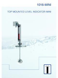
Transcription of VM - 1 Magnetic Level Indicator
1 An CompanyVM - 1 Magnetic Level IndicatorOPERATING INSTRUCTIONS 13964 South Wayside Houston, TX 77048 USA Tel: 877-411-Vize (8493) VM-1 Series Installation, Operation and Maintenance Instructions Contents Section Magnetic Level Gauges Description Introduction Components Chamber Material Internal Float Float Submergence GAUGE ratings Hydrostatic Testing Level Indication Introduction Flag/Flipper Indication (FL) Flag/Flipper Indication - Reference Guide Flag /Flipper Indication - Retrofit Installation Inspection Chamber Orientation Connection Valves Float Orientation Chamber Gaskets Flanges and Connections Interface Applications Operation Introduction Procedures Introduction Procedures Removal from Service Introduction Procedures Appendix I Flange to Flange Connections430-00 11/12/07 13964 South Wayside Houston, TX 77048 USA Tel: 877-411-Vize (8493) Installation, Operation and Maintenance Instructions Contents Section Magnetic Level Gauges (cont.)
2 Maintenance Introduction Procedures Troubleshooting Introduction Float & Indicator Detachment Differential Level Defective Indicator Parts List Introduction Chamber Indicator & Scale Assembly Warranty Introduction Conditions Provisions Terms and Condition of Sale Introduction Terms Shipment Restocking Cancellation 13964 South Wayside Houston, TX 77048 USA Tel: 877-411-Vize (8493) Magnetic Level Gauges Installation, Operation and Maintenance Instructions Section - Description INTRODUCTION Vize Magnetic Level gauges (VM-1) are an indirect reading liquid Level Indicator . The Magnetic Level gauge series utilize non- Magnetic , schedule 40 chambers (standard). Vize manufactures these chambers to length specifications with process connections that match those of the vessel or tank. For some high pressure, low gravity applications, a - schedule 40 chamber is available. The process connections may be: 1.
3 Side mounted , threaded, flanged or socket welded 2. Top and bottom flanged mounted 3. Tank top mounted 4. Combination A variety of mounting styles is available to suit any vessel or piping requirements. Refer to the drawing depicting Magnetic Level gauge mounting configurations. COMPONENTS The gauge chamber contains a Magnetic float and is completely isolated from the Indicator housing attached to the outside of the gauge chamber. External indicators are continuous flag/flipper models. The Magnetic float maintains a Magnetic bond with the external Level Indicator . As the Level of the process medium fluctuates within the tank and gauge chamber, the float reacts accordingly with the Indicator recording the Level of the fluid within the chamber. CHAMBER MATERIAL Vize manufactures gauges to meet exact specifications of the process media such as operating pressure, temperature, specific gravity, etc. Standard chamber materials are 316/304 stainless Steel, but any non- Magnetic material may be used.
4 Other chamber materials that are available include Alloy 20, Hastelloy, Zirconium, Monel, Kynar, and CPVC. INTERNAL FLOAT The float chamber houses a magnetized float, designed to the requirements of the process conditions, inside. For this reason, floats are not interchangeable unless the process conditions and gauge chambers are identical. The float moves freely inside the chamber reacting to fluctuating Level changes within the adjoining vessel. 13964 South Wayside Houston, TX 77048 USA Tel: 877-411-Vize (8493) Magnetic Level Gauges Installation, Operation and Maintenance Instructions Section Description (cont.) FLOAT BUOYANCY Under normal operating conditions, the process fluid should cover the float about 80% or more. NOTE: The position of the float in the media will vary with different process conditions. Float magnets are located in the upper portion of the float. GAUGE RATINGS Vize can design Magnetic Level gauges for operating conditions from full vacuum service up to 2500 PSIG, 900 F, and a minimum specific gravity of Generally, Magnetic gauges with alloy chambers will have full ratings based on flange classifications.
5 Gauges with Kynar, CPVC, or Fiberglass shields will have 150 PSIG ratings only. HYDROSTATIC TESTING Gauge chambers receive hydrostatic testing to 150% of indicated gauge rating WITHOUT floats installed. Floats receive individual testing. Gauges can be field hydrostatically tested after installation at the operator's discretion. CAUTION: Do not conduct hydrostatic testing of the Magnetic gauge chamber attached to a process vessel with the float installed. If a gauge is field tested with the float installed, the float may crush and the chamber may become damaged. This procedure will void the warranty. 13964 South Wayside Houston, TX 77048 USA Tel: 877-411-Vize (8493) Magnetic Level Gauges Installation, Operation and Maintenance Instructions Section - Level Indication INTRODUCTION Vize offers the wide flag Indicator (WF)(SWF) to meet your process Level indications. WIDE FLAG/FLIPPER INDICTION (WF)(SWF) Vize offers a continuous Wide Flag or Flipper style Indicator as an option to the Single Yellow Follower Indicator .
6 Flag indicators are industrial grade Level indicators, which consist of a series of Amodel flags, black on one side, yellow on the other. As the Magnetic float reacts to Level fluctuations, each flag or flipper will rotate 180 degrees to reveal the opposite color. Vize flippers reside in a rugged sealed housing with a recessed polycarbonate window. The flippers rotate on a HDPE surface. This rotation prevents the flippers from sticking or hanging up. This unique design prevents all flippers from rotating in excess of 180 degrees and locks each flag magnetically to the next flag. Each flag Indicator is inches wide and is more visible than a single Indicator . The flag indicators are available with or without scales in unlimited lengths. WIDE FLAG/FLIPPER INDICATION - REFERENCE GUIDE Yellow represents liquid column. Black represents vapor space. Other colors are available. WIDE FLAG/FLIPPER INDICATION - RETROFIT When purchasing flag style indicators with a Vize Magnetic Level gauge, no installation is necessary.
7 If you remove the Indicator or purchase a retrofit kit for a gauge already in service, note the following information: 1. The mounting clamps connecting the flipper assembly to the gauge chamber are adjustable to most manufacturers' standard, such as a inch to a pipe. If the gauge is in service and there is liquid in the tank, when you clamp on the Indicator assembly, only the flippers adjacent to the float will rotate to yellow. 2. Run a magnet along the window of the Indicator from zero to where yellow is showing as noted. 3. Drain the gauge to zero on the Indicator , and re-fill again. As the float rises, the Level Indicator reacts accordingly and resets properly. 13964 South Wayside Houston, TX 77048 USA Tel: 877-411-Vize (8493) Magnetic Level Gauges Installation, Operation and Maintenance Instructions Section Installation INSPECTION Vize securely packs all Magnetic Level indicators in crates to provide maximum protection of the equipment during shipment.
8 Make certain you unpack and inspect each gauge upon receipt to ensure the Indicator and chamber received no damaged in shipment. If you find damaged parts, contact Vize immediately. Vize fully insures all Magnetic gauges against damage or loss unless specified by the customer otherwise. You must file any claims within five (5) days from the date of receipt of the shipment. CHAMBER ORIENTATION Remove the Magnetic float, packaged separately in the shipment crate, before installation. Make sure you Level the float chamber vertically. If you do not Level the float correctly, the float may be magnetically uncoupled from the Level Indicator during operations. CONNECTION VALVES Install valves between the process vessel and Level gauge to allow for isolation, draining, and cleaning purposes. (See section on Maintenance for more details on cleaning and maintenance procedures). You can order standard block valves with the gauge or you can order the valves separately from Vize.
9 Ball check valves are not necessary for Magnetic Level gauges. If certain valve specifications are required, please advise Vize accordingly. FLOAT ORIENTATION The internal Magnetic float has a preferred orientation of vertical. An inscription at the top of the float indicates this orientation. If you install the float into the chamber inverted, it will not couple with the external Indicator correctly and result in improper Level indication. Floats installed in gauges with inverted chamber construction will contain a loop at the top of the float for installation and removal purposes. NOTE: Do not install internal floats until any hydrostatic field tests of the chamber and connecting vessel are complete. 13964 South Wayside Houston, TX 77048 USA Tel: 877-411-Vize (8493) Magnetic Level Gauges Installation, Operation and Maintenance Instructions Section - Installation (cont.) CHAMBER GASKETS Standard Magnetic Level gauges include composition gaskets.
10 If this type of gasket is not compatible with the process media, make sure you use the appropriate gaskets instead of those shipped with the gauge. FLANGES AND CONNECTIONS Vize designs process connections and vent/drain flanges to meet each customer's specifications. All flange bolt holes straddle the centerline unless otherwise specified. Both male and female threaded connections and socket weld connections are available. INTERFACE APLICATIONS You can use Magnetic gauges to identify fluid interfaces only if you have identified the proper specific gravities at the maximum operating conditions. Vize can design the float to sink in one media while floating in another media. Immiscible oil over water levels is an example. Exercise caution when using Magnetic gauges in interface applications because rag layers, which are difficult to identify may exist. 13964 South Wayside Houston, TX 77048 USA Tel: 877-411-Vize (8493) Magnetic Level Gauges Installation, Operation and Maintenance Instructions Section - Operation INTRODUCTION Make certain you thoroughly read all instructions pertaining to entering Magnetic Level gauges into service before commencing with service operations.