Transcription of Volume 3, Issue 3, September 2013 Power Control …
1 ISSN: 2277-3754. ISO 9001:2008 Certified International Journal of Engineering and Innovative Technology (IJEIT). Volume 3, Issue 3, September 2013 . Power Control of DFIG Using Back to Back Converters (PWM Technique). Parminder Singh*, Gagandeep Sharma**, Sushil Prasher**. *Student (M-tech), Department of Electrical Engineering, DAVIET, Jalandhar ** (Assistant professor, Department of Electrical Engineering, DAVIET, Jalandhar ** (Assistant professor, Department of Electrical Engineering, DAVIET, Jalandhar 1. Control Circuits Abstract :- Wind is one of the most widely used non- 2. Operating Modes conventional sources of energy. A back-to-back PWM 3. Convertor Types converter is used as the excitation Power supply for the doubly 4. Protection Circuits fed induction generator (DFIG) wind Power generation of variable speed constant frequency (VSCF).The Simulink II. DIFFERENT TECHNOLOGIES. model and Control strategy of converter which is connected CATEGORIZATION. between rotor and grid is analyzed.))
2 Stator-flux oriented vector Control approach is used for both stator and rotor side For a variable-speed wind Power system, the generator converter has been proposed. Taking this into account is connected to the grid through Power electronic Performance of double fed induction generator (DFIG) converters connected back-to-back [8]. The converter is variable speed wind turbine under network fault is studied needed because the variable speed generator produces a using simulation developed in MATLAB/SIMULINK results variable frequency voltage that has to be converted to show the transient behavior of the doubly fed induction match the constant grid frequency. The generators used generator when a sudden short circuit at the generator. After may be squirrel cage induction generator, permanent- the clearance of short circuit fault, the Control Schemes magnet synchronous generator or Doubly-Fed Induction manage to restore the wind turbines normal operation. On the Generator (DFIG).
3 For the squirrel cage and the rotor side fluctuations in torque, wind speed, Stator current and rotor current are noticed whereas on the Grid side permanent-magnet generators, the back-to-back variations in active Power and reactive Power is seen with converters are connected to the stator where high Power voltage and current. is flowing, so the converters have to be high rated and this is its drawback. The Power converters are connected Keywords Active and reactive Power , Back to Back to the rotor in the DFIG configuration and need to carry converters, DFIG, IGBT, Simulink model. only the slip Power . The stator is directly connected to the grid while the rotor is connected to the grid through back I. INTRODUCTION. to- back converters, rotor side and grid side converters Wind energy plays an increasingly important role in [5], [6]. A vector Control is employed to Control the DFIG. the world because it is friendly to the environment during in order to decouple the active and reactive Power flow the last decades; the concept of a variable-speed wind between the generator and the grid.
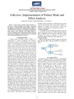
4 Wind turbines use a turbine (WT) has been receiving increasing attention due doubly-fed induction generator (DFIG) consisting of a to the fact that it is more controllable and efficient, and wound rotor induction generator and an AC/DC/AC. has good Power quality. As the demand of controllability IGBT-based PWM converter. of variable speed WTs increases, it is therefore important and necessary to investigate the modeling for wind turbine-generator systems (WTGS) that are capable of accurately simulating. In order to obtain satisfying output Power from the WTGS, Control strategies are also necessary to be developed based on the previously obtained WTGS models [1]. These Control schemes include the grid-side converter Control , the generator-side converter Control , the maximum Power point tracking Control and the pitch angle Control . The grid-side converter controller is used to keep the DC-link voltage constant and yield a unity Power factor looking into the WTGS from the grid-side.
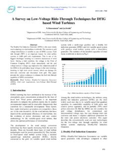
5 The generator-side converter Fig 1 : Different Technology Categorization[7]. controller has the ability of regulating the torque, active The stator winding is connected directly to the 50 Hz Power and reactive Power . The maximum Power point grid while the rotor is fed at variable frequency through tracking Control is used to provide the reference values the AC/DC/AC converter. The DFIG technology allows for the active Power at the stator terminals. Following are extracting maximum energy from the wind for low wind the different technology categorization for DFIG:- speeds by optimizing the turbine speed, while minimizing mechanical stresses on the turbine during gusts of wind. 196. ISSN: 2277-3754. ISO 9001:2008 Certified International Journal of Engineering and Innovative Technology (IJEIT). Volume 3, Issue 3, September 2013 . Another advantage of the DFIG technology is the ability Xs Slope or droop reactance ( ). for Power electronic converters to generate or absorb Pnom Three-phase nominal Power of the converter reactive Power , thus eliminating the need for installing specified in the block dialog box capacitor banks as in the case of squirrel-cage induction When the wind turbine is operated in var regulation generator.
6 Mode the reactive Power at grid terminals is kept constant by a var regulator. The output of the voltage regulator or III. FOR ROTOR SIDE Control . the var regulator is the reference d-axis current Idr_ref The Control strategy made for the machine side that must be injected in the rotor by converter Crotor. The converter is shown in The main purpose of the same current regulator as for the Power Control is used to machine side converter is to maintain the rotor speed regulate the actual Idr component of positive-sequence constant irrespective of the wind speed and also the current to its reference value. The output of this regulator Control strategy has been implemented to Control the is the d-axis voltage Vdr generated by Crotor. The current active Power and reactive Power flow of the machine regulator is assisted by feed forward terms which predict using the rotor current components. The active Power Vdr. Vdr and Vqr are respectively the d-axis and q-axis of flow is controlled through idr and the reactive Power flow the voltage Vr.
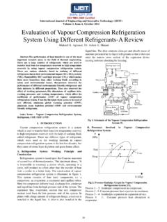
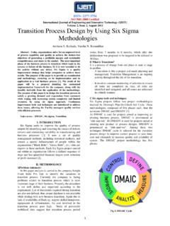
7 Is controlled through iqr. To ensure unit Power factor operation like grid side converter the reactive Power demand is also set to zero here. The standard voltage oriented vector Control strategy is used for the machine side converter to implement Control action. Here the real axis of the stator voltage is chosen as the d-axis. The vector diagram is shown in Fig. rotor-side converter is used to Control the wind turbine output Power and the voltage measured at the grid terminals. The Power is controlled in order to follow a pre-defined Power -speed characteristic, named tracking Fig 3 Simulink model for DFIG(Rotor Side). A. Results under normal condition Under the normal condtion, DFIG works under no load condition and and having no fault on the rotor side. Fig 4. shows the waveforms for rotor and stator currents wherseas Fig 5 shows the waveforms for wind speed and torque produced by doubly fed induction generator. Fig 2 Rotor converter Control block diagram[2]. For the rotor-side controller the d-axis of the rotating reference frame used for d-q transformation is aligned with air-gap flux.
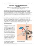
8 The actual electrical output Power , measured at the grid terminals of the wind turbine, is added to the total Power losses (mechanical and electrical) and is compared with the reference Power obtained from the tracking characteristic. A Proportional- Integral (PI) regulator is used to reduce the Power error to zero. The output of this regulator is the reference rotor current Iqr_ref that must be injected in the rotor by converter Crotor. V= Vref. + I* Xs where, V Positive sequence voltage ( ) Fig 4 :Stator & Rotor currents I Reactive current ( ) (I > 0 indicates an inductive current). 197. ISSN: 2277-3754. ISO 9001:2008 Certified International Journal of Engineering and Innovative Technology (IJEIT). Volume 3, Issue 3, September 2013 . Fig 7: variation in Torque and wind speed IV. GRID SIDE Control . Fig 5: Variation in Torque and Rotor speed The Grid side converter is used to regulate the voltage of the DC bus capacitor. For the grid-side Controller the B. Results under fault condition (Double phase to d-axis of the rotating reference frame used for d-q ground Fault) transformation is aligned with the positive sequence of In this section Double phase to ground fault is put on to grid voltage.
9 This controller consists of:- the rotor side of doubly fed induction generator. The 1. A measurement system measuring the d and q variation in stator current and rotor currents are shown by components of AC currents to be controlled as well as the fig 6, and variations in wind speed and torque are shown DC voltage Vdc. in fig 7. 2. An outer regulation loop consisting of a DC voltage Regulator. 3. An inner current regulation loop consisting of a current Regulator. Fig 8 Simulink model for Grid side Control The current regulator controls the magnitude and phase of the voltage generated by converter Cgrid (Vgc) from the Idgc_ref produced by the DC voltage regulator and specified Iq_ref reference. The current regulator is assisted by feed forward terms which predict the C grid Fig 6: Stator & Rotor currents output voltage. Fig 9: Grid side controller [5]. 198. ISSN: 2277-3754. ISO 9001:2008 Certified International Journal of Engineering and Innovative Technology (IJEIT). Volume 3, Issue 3, September 2013 .
10 Fig 10: Pitch angle Control method [5]. The pitch angle is kept constant at zero degree until the speed reaches point D speed of the tracking characteristic. Beyond point D the pitch angle is proportional to the speed deviation from point D speed. For electromagnetic transients in Power systems the pitch angle Control is of less interest. The wind speed should be selected such that the rotational speed is less than the speed at point D. A. Results for Grid side Control under Steady state conditions Whenever there is any Variations occur on the grid Fig 13: Variation in Active & Reactive Power side on the doubly fed induction generator it will create B. Results for Grid side Control under Transient effects on the active and reactive Power of the DFIG and conditions also affects the voltage and current. The fig 11 and 12. reveals the waveforms of Voltage and current respectively under normal conditions whereas Fig 13. shows the waveforms for active and reactive Power . Fig 14: Change in Vabc Fig 11: Change in Vabc Fig 15: Change in Iabc (current).