Transcription of Volume 3, Issue 9, March 2014 Adaptive Side lobe …
1 ISSN: 2277-3754. ISO 9001:2008 Certified International Journal of Engineering and Innovative Technology (IJEIT). Volume 3, Issue 9, March 2014 . Adaptive Side lobe Jamming Cancellation for Low altitude radar Habib Rezaei, Mohsen Mivehchy, Saied Ali Hashemi receiver signals at I and Q signals (Quadrature) of side Abstract Side lobe jamming technique is a safe method that receiver, the phase difference between the main signal and prevents detection of interference source. Side lobe cancellation side I and Q signals are extracted. With a weight ratio the two can be efficiently employed to reduce the effects of jammers on side receiver signals, I and Q are gathered and produce a radar systems through antenna side lobes.
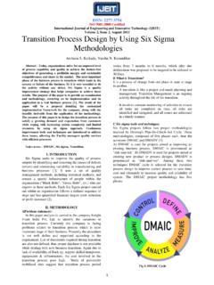
2 The feedback control method doesn't require any components with a high dynamic signal which has the same power and phase as the main range for reduction of side lobes, which is suitable for analogous interfering signal. By subtracting generated signal from the processing. The feedback control enables us to reducing the side main receiver, the interference signal is removed from main lobes interference up to 40dB. In this method, by comparing the signal, and only the target signal remains in the main receiver. main receiver signal with the side receiver signal, Phase and The block diagram of this method is shown in power difference between the signals can be determined.
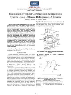
3 Side receiver signal is collected by a weighting factor whit main P. receiver signal, to cancel the side lobes interference. X . Index Terms Radar, Side lobes cancellation, Jamming, ECCM. VaN. M N X. X . I. INTRODUCTION. U + S. Today's radar systems are powerful in battlefield, therefore HARD. during the war, disrupting the radar systems is an important LIMIT +. VaN* U*. goal. Side lobe jamming technique is a safe method that 1 /2 X. M* . N*. prevents detection of interference source, and can be X. /2. influence the radar performance in wide angle. The radar antenna pattern has side lobes in addition to the main lobe, Va Zn Pn 20 . which have lower gain and different propagation direction.
4 Than the main lobe. In designing antenna, whenever it is 0. Z. possible, the side lobes number and pattern power have to be Vm - . reduced. Side lobe canceller system, reduces radar side lobe + OUT. effect by auxiliary antennas in addition to the main antenna. The radars usually have one or more auxiliary antenna, which Fig 1. SLC block diagram are aligned with the main antenna. The width of the main lobe of the auxiliary antenna is bigger than the whole radiation area If side receiver signal is given by Va, then Va can be of each of main radar antenna side lobes. This antenna main represented by(1): lobe gain is more than any main antenna side lobes.
5 Every signal which is received by the side lobes of main antenna is Va BCos( t ) (1). received with the further gain by the auxiliary antenna. Side J. lobe canceller system can be efficiently employed to reduce B=Jamming signal amplitude coefficient at side receiver the effects of jammers on a radar system through antenna side J =Jamming frequency lobes. When comparing the main receiver power with the side Side receiver signal is hard limited for attenuation receiver's power, if the side receiver's power is more than the amplitude variations in the side receiver signal. By placing a LPF after this system, the high frequency component is main receiver's, then signal has been received by the side removed and amplitude of the output signal is fixed.
6 The lobes. remained signal is VaN ,The amount is by (2) equal to: II. FEEDBAK CONTROL METHOD FOR SIDE LOBE Va Cos( J t ) (2). N. CANCELLATION P obtained from multiplying the side receiver signal and The purpose of SLC is reducing the interfering signal from side limited signal.[2] (Side receiver signal power can be radar's main receiver, and the real target signal remains intact. extracted by Log Amp chips.). In this method the power difference between the side and main receiver is determined and with multiplying the main 272. ISSN: 2277-3754. ISO 9001:2008 Certified International Journal of Engineering and Innovative Technology (IJEIT).
7 Volume 3, Issue 9, March 2014 . P Va N Va 20 A. N cos (9). 2 BD. BCos( J t ) (3).. [ 1 Cos 2( J t )] M* is the value of ZN signal multiplied by shifted VaN. The P B 2. 2 value of M * is given by (10): If a low-pass filter is placed at the output P, the high M* Z N Va* . frequency component is filtered and the remaining amount is the side receiver voltage amplitude. According to (4) the 40 A. amount of Pn is: Sin( J t ) cos ( J t ) . B D. B. Pn (4) 40 H. 2 Sin( J t )Cos( J s )t (10). B K. If the target signal is accompanying the interfering signal in the main receiver and coefficient of the target signal amplitude is equal H; then the main receiver signal can be 20 A.
8 Sin Sin( 2 J t ) . BD. shown by (5): Vm A cos ( J t ) HCos( J s )t (5). 20 H.. Sin( s t ) Sin(( 2 J s )t ) . BK. A=Jamming signal amplitude If M* filtered by a LPF, high frequency components are S=frequency difference between jamming and target signal removed, and low frequency signal is remained. That shown in Z is the output of SLC system, which the by N*. interfering signal is canceled. 20 A. A H N* Sin (11). Z cos ( J t) Cos( J s )t (6) BD. D K A limiter, limits the output of the N and N* between [ ]. D= interference signal attenuation This limiter will prevent the reduction of the target signal in K=target signal attenuation the absence of interference.
9 U is the product of multiplying Zn is the normalized output Z which is amplified by factor phase difference signals (N) by side receiver signal (Va). The 20and normalized by Pn. ZN value according to (7) is: value of U is given by (12): Z 20. ZN U Va N . 20 A. cos ( J t ) Cos (12). Pn (7) D. 40 A 40 H U* is the product of phase signal difference (N*) by cos ( J t ) Cos( J s )t B D B K . If ZN and VaN have equal frequency and phase difference, shifted side signal (Va*). The value of U* is given by (13): 2. multiplied to each other, the output value is a function of the phase difference between two signals and ZN signal power. M 20 A.
10 U* Va* N* Sin( J t ) Sin (13). is the phase difference between ZN and VaN. M value D. according to (8) is: The sum of U and U* signals are shown in by S, M Z N Va and it is generated by SLC system in order to cancell the N. interference from main receiver's signal. In Figure 2 it is 40 A shown how to sum I and Q signals. The value of S is given by cos ( J t ) cos ( J t ) . B D equation 14:[7]. S U U* . 40 H. B K. cos ( J t )Cos( J s )t (8).. 10 A cos ( J t ) Cos( J t ) . (14). D cos ( J t ) Cos( J t ) . 20 A. cos cos ( 2 J t ) . BD. 20 A 20 A. Cos J t S . cos ( s ) cos (( 2 J s )t ) . 20 H Cos J t D D. BK. If M filtered by a LPF, High frequency components are removed, and low frequency signal is remained.