Transcription of Volute Casing Centrifugal Pumps SERIES NB Block Design
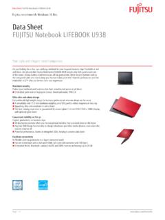
1 Volute Casing Centrifugal Pumps SERIES NB. Block Design Application Combination of components For pumping pure water, industrial water, sea water, con- The table on page 3 shows the combination possibilities of densates, oils, brines, lyes and hot water. components of all NB sizes. The unit assembly system allows The fluids to be pumped must not contain any abrassive parti- reduced stock keeping of spare parts. cles nor chemically attack the pump materials. Explosion protection Main fields of application The pump fulfils the requirements according to EC. In cooling and heating systems, in circulating, water supply, Explosion Protection Directive 2014/34/EU (ATEX. water treatment, sea-water desalination, dedusting and 100a) for equipment and equipment group II, category spray painting plants as well as in air-conditioning, cooling, 2 G. Categorisation into temperature classes according to DIN.
2 Swimming pool and industrial engineering. EN 13463-1 depends on the temperature of the pumped me- dium. The max. permissible temperature of the pumped medi- Design and SERIES construction um for the respective temperature classes are shown in the Volute Casing Centrifugal pump, single entry, single or two- specific order data sheet. stage, of Block Design . Pump size according to DIN EN 733. Note: In case of the operation of a category 2 pump, the un- Stub and motor shaft are rigidly coupled together. Shaft bear- acceptable heating of the pump surfaces caused by a possible ing in the motor by means of grease-lubricated groove ball operational fault must be prevented by a control mechanism. bearings. The mating dimensions of the two-stage sizes In case of an operation with constant parameters (pressure, 2/25 200, 2/32 200, 2/40 250, 2/50 250, except for dimen- temperature, speed = const.)
3 , a pump performance controller sions f and l depending upon the driving motors, correspond to can be supplied with the pump to detect any operational faults. the single-stage designs. Volute Casing with feet cast on. Drive Horizontal or vertical installation, motor arrangement down- Surface-cooled three-phase squirrel-cage induction motors, wards is not admissible. with locating-type bearing, IM V1 type of construction, en- closure IP55 according to IEC Standard, class F insulation, Performance data performances and main dimensions according to DIN EN. Delivery Q up to 480 m3/h 50 347, up to kW 230/400V, from kW 400/690 V. Delivery head H up to 145 m Temperature of the fluid pumped t up to 140 C Attention: Motors provided by customers must also have a Inlet pressure ps locating-type bearing! Pump outlet pressure as a function of the shaft diameter Dismantling the driving unit and the shaft seal When dismantling the driving unit, the Volute Casing may re- with diameter 16, 24, 30 pd up to 16 bar main in the piping.
4 With diameter 40 pd up to 10 bar Connections Drive power P 0,25 up to 37 kW The following auxiliary connections are always provided: Nominal diameter, delivery flange DNd 25 up to 150 FD1 Draining FV1 Venting Branch position/flanges optional FF1 Filling Suction branch: axial PM1 Pressure measurement pump Delivery branch: radially upwards PM2 Pressure measurement pump Flanges: up to DN 150 acc. to DIN EN 1092-2 PN 16 inlet pressure plus maximum delivery head must not exceed the admissible as from DN 200 acc. to DIN EN 1092-2 pump outlet pressure PN 10 / PN16 allocation pump size / shaft diameter at the shaft seal, refer to pages 12 to 19. Contact protection in case the temperature of fluids pumped exceeds 120 C, the admis- sible pump outlet pressure changes as follows: The requirements of DIN EN 809 Contact protection , are met. flange-mounted PN16. Shaft seal flange-mounted PN10.
5 By maintenance-free mechanical seal in unbalanced Design (main dimensions acc. to DlN EN 12 756, Design K, shape U). connection FF1 at sizes 20-160; 25-200 und 2/25-200 not existent; failure at connection PM2 possible VM 528 Ident No. 795261 1. Shaft seals with temperature and pressure limits Available for all material designs Mechanical seal, uncooled Unbalanced Flushing Internal flushing Abbreviation U3D U Hard carbon, Hard carbon, Rotating seal ring Silicon carbide synthetic resin impregnated antimony impregnated Stationary seal ring Oxide ceramics Silicon carbide Metal parts CrNiMo steel CrNiMo steel O-rings EPDM FPM EPDM FPM EPDM. Bellows - - EPDM FPM - Material key, BVEGG BVVGG Q1Q1 EGG Q1Q1 VGG AQ1 EGG. DIN EN 12 756. Volute Casing Centrifugal Admissible temperature of the fluid pumped ( C) and admissible pump outlet pressure pd (bar)). Pumps at bearing bracket size C / bar C / bar C / bar C / bar C / bar single-stage 100 / 10 100 / 10 100 / 10 100 / 10 140 / 10.
6 Two-stage 100 / 16 100 / 16 100 / 10 100 / 10 140 / 16. applies to water max. 90 C. only possible for sizes with shaft diameters 16, 24, 30 (at the shaft seal). in case of inlet pressure > 5 bar, shaft seal D or K must be provided, optional shaft seals , and possible. Other mechanical seal designs on inquiery. Abbreviation system NB 40 - 200 / 01 / 180 U3D - W133 - 38 / 300. SERIES Standard nominal width on delivery side Size . Nominal impeller diameter Hydraulic no. Actual impeller diameter . Shaft seal Material Design Stub shaft bore diameter for fixing to motor shaft end Drive lantern or intermediate ring outside diameter or flange size of electric motor The actual impeller diameter of two-stage sizes relates to the second stage. The number of stages is placed in front of the nominal width of the outlet branch, 2/40 200/.. Materials Part No. Material designs Denomination single- two-stage W 133 W 134 W 135 W 149 W 152.
7 Stage EN-GJS-400-18- EN-GJS-400-18- Volute Casing G-CuAl10Ni EN-GJS-400-15 EN-GJS-400-15. LT LT. Impeller - G-CuAl10Ni G-CuAl10Ni EN-GJL-200 G-CuAl10Ni EN-GJL-250. Impeller 1st G-CuAl10Ni EN-GJL-250. - G-CuAl10Ni G-CuAl10Ni EN-GJL-200. stage Impeller 2nd G-CuAl10Ni EN-GJL-250. - G-CuAl10Ni G-CuAl10Ni EN-GJL-200. stage Diffuser - G-CuAl10Ni G-CuAl10Ni EN-GJL-200 G-CuAl10Ni G-CuAl10Ni EN-GJS-400-18- EN-GJS-400-18- Stage Casing - G-CuAl10Ni EN-GJS-400-15 EN-GJS-400-15. LT LT. EN-GJS-400-18- EN-GJS-400-18- Casing cover l G-CuAl10Ni EN-GJS-400-15 EN-GJS-400-15. LT LT. Stub shaft X2 CrNiMoN225 X2 CrNiMoN225 X2 CrNiMoN225 X2 CrNiMoN225 X2 CrNiMoN225. EN-GJL-250 or EN-GJL-250 or EN-GJL-250 EN-GJL-250. Drive lantern EN-GJL-250. steel steel EN-GJS-400-18- EN-GJS-400-18- Intermediate ring - G-CuAl10Ni EN-GJS-400-15 EN-GJS-400-15. LT LT. EN-GJS-400-18- EN-GJS-400-18- Intermediate ring - G-CuAl10Ni EN-GJS-400-15 EN-GJS-400-15.
8 LT LT. 2 VM 528 Ident No. 795261. Combination of components The following table shows the combination possibilities of components or spare parts of the NB sizes. Within a vertical column, parts with identical numbers are interchangeable. Shaft Pump size Volute Impeller Impeller Diffuser Stage Inter- Casing Stub shaft Drive Intermediate diameter at NB Casing Casing mediate cover lantern ring the shaft seal ring 1st 2nd stage stage The allocation to the sizes depends on speed, motor mm performance and motor Design 16-14 16-160. 16-19. 16 20-160 1 1 - - - - - 1 16-200 - 16-24. 16-250. 16-28. 32-125 2 2 24-14 24-160. 24-19. 40-125 3 3 24-200. 24-24. 24 - - - - - 2 24-250 - 50-125 4 4 24-28. 24-38 24-300. 65-125 5 5 24-42 24-350. 25-160 6 6. 25-200 7 7 30-19. 32-160 8 8. - 30-200. 32-200 9 9 30-24. 40-160 10 10. 30-250. 30-28. 40-200 11 11. 40-250 12 12 1.
9 30 - - - - 3 30-38 30-300 - 50-160 13 13. - 50-200 14 14. 30-42. 30-350. 50-250 15 15 1. 65-160 16 16 - 30-48. 30-400. 65-200 17 17 1. 80-160 18 18 30-55. - 100-160 19 19. 2/25-200 7 - 2/30-19. 30-200. 1 1 1 1 4 2/30-24. 2/32-200 9 - 2/30-28 30-250. 30. - 2/30-38 30-300 - two-stage 2/40-250 12 - 6 2/30-42 30-350. 6 2 2 5 2/30-48. 2/50-250 15 - 3 2/30-55 30-400. 65-250 20 20 - 65-315 21 21 2. 65-400 22 22 3 40-28. 80-200 23 23. - 80-250 24 24 40-38. 80-315 25 25 2 40 - - - - 6 40-360. 100-200 26 26 40-42. - 100-250 27 27. 100-315 28 28 2 40-48. 125-200 29 29. 125-250 30 30 - 40-55. 150-200 31 31. VM 528 Ident No. 795261 3. Benefits Uncooled, unbalanced mechanical Commercial standard motors Horizontal and vertical mount- seal for cavities according to with locating-type bearing, con- ing possible with exception of DIN EN 12 756, Design K, form U. struction IM V1, all types of en- motor downward.
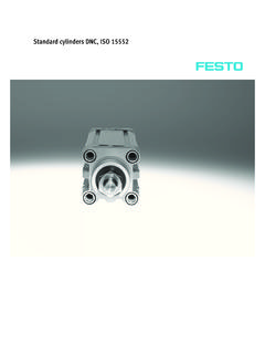
10 Closures and speeds of rotation possible. Negligible axial thrust by fine Optimized hydraulic with very When dismantling the driving adaption of the balancing holes. good efficiencies and NPSH- unit (including impeller) the values of the standard SERIES Volute Casing remains in the NT acc. to DIN EN 733, deliv- piping. ery rate partly considerable above the standard de- mands Larger delivery heads with two-stage sizes (2/25-200, 2/32-200, 2/40-250, 2/50-250). The outer dimensions corre- spond with the single stage Design . 4 VM 528 Ident No. 795261. Performance graphs Refer to the individual curves for precise performance data. Valid for = 1 kg/dm and = 1 mm /s. VM 528 Ident No. 795261 5. Refer to the individual curves for precise performance data. Valid for = 1 kg/dm and = 1 mm /s. 6 VM 528 Ident No. 795261. Sectional drawing Single-stage sizes with shaft diameter 16 at the shaft seal Fixing of guard plate to the drive lantern.