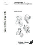
Transcription of Vortex Flow Measuring System TI 062D/24/ae …
1 Technical Information TI 062D/24/ae Vortex Flow Measuring System PROline prowirl 72. Reliable Flow Measurement of Gas, Steam and Liquids Application Your benefits For Measuring the volume flow of steam, Proven capacitive sensor gases and liquids. (installed base > 100,000). For utility and process applications in the Immune to: chemical, petrochemical, power and Vibration (over 1 g in all axes). district heating industries and in many Temperature shock (> 150 K/s). other industries. Dirty media Water hammer Process temp. range -330 to +750 F. (-200 to +400 C). Universal: Compact or remote version Dualsens version, with two sensors and electronics (for redundancy). Alloy C-22 version Connection to all common systems: HART. PROFIBUS-PA. FOUNDATION Fieldbus Galvanically isolated pulse output available (for alarm, limit value etc.). Permanent self-monitoring and diagnosis of electronics and sensor. Correction of diameter mismatch.
2 No maintenance, no moving parts, no zero-point drift. PROline prowirl 72 F, W. Function and System design Measuring principle The operating principle is based on the Karman Vortex street. When a fluid flows past a bluff body, vortices are alternately formed on the sides of that body and are then dectached or shed by the flow. The frequency of Vortex shedding is proportional to the mean flow velocity and, therefore, to the volumetric flow. Alternating pressure changes caused by the vortices are transmitted by the sensor. The DSC sensor is located behind the bluff body and is well protected from water hammer and temperature or pressure shocks. v The K-factor is used as the proportional constant: pulses pulses K-Factor = OR K-Factor =. unit volume [gal] unit volume [dm ]. Within the application limits of the device, the K-factor only depends on the geometry of the device. It is independent of the fluid velocity and its properties viscosity and density.
3 In this way, the K-factor is also independent of the type of fluid to be measured, regardless of whether this is steam, a gas or a liquid. The primary Measuring signal is already digital (frequency signal) and a linear function of the flow. After manufacturing the meter, the K-factor is determined in the factory by means of calibration and is not subjected to any long term drift or zero point shift. The device does not contain any moving parts and requires no maintenance. The capacitive sensor The sensor of a Vortex flowmeter has a major influence on the performance, robustness and reliability of the whole Measuring System . The prowirl 72 uses Endress + Hauser's proven and patented capacitive Measuring technology, with more than 100,000 Vortex Measuring points installed to date world wide. Due to its internal mechanical balance, the DSC sensor (Differential Switched Capacitance), reads only the pressure pulses caused by the Sensor vortices and stays immune to any influence from mechanical pipe line vibrations.
4 The DSC sensor measures low flow rates at low fluid density even when pipe line vibrations are present. Therefore, the prowirl 72 keeps its wide turndown ratio even under rough operating Seal conditions. Z-Axis Vibrations of at least 1g at frequencies up to 500 Hz in all axes do not affect the flow Y-Axis measurement. Thanks to its mechanical design, the capacitive sensor is especially resistant to temperature shocks and water hammer in steam lines. X-Axis 2 Endress + Hauser PROline prowirl 72 F, W. Measuring System The Measuring System consist of a sensor and a transmitter. Two versions are available: Compact version: sensor and transmitter form a mechanical unit. Remote version: sensor is mounted separate from the transmitter. Sensor prowirl F 1/2 to 12 (DN 15 to 300). Flanged version (also available as version with two sensors and electronics for redundancy, 1-1/2 to 6 / DN 40 to 150). prowirl W 1/2 to 6 (DN 15 to150).
5 Wafer version Transmitter prowirl 72. Input Measured variable Volumetric flow (volume flow), is proportional to the frequency of Vortex shedding after the bluff body. The output variables are volume flow or, if the process conditions are non-varying, calculated mass flow or corrected volume flow. Measuring range The Measuring range depends on the fluid and the nominal diameter. Start of Measuring range Depends on the density and the Reynolds number (Remin = 4,000, Relinear = 20,000). The Reynolds number is dimensionless and indicates the ratio of a fluid's inertial forces to its viscous forces. It is used to characterize the flow. The Reynolds number is calculated as follows: 4 Q [ft /s] [lb/ ft ] 4 Q [m /s] [kg/ m ]. Re = Re =. di [ft] [ cP] di [m] [Pa s]. Re = Reynolds number; Q = Flow; di = Internal diameter; = Dynamic viscosity; = Density 1/2 to 1 v min. = [ft/s] 1-1/2 to 6 v min. = [ft/s]. [lb/ft ] [lb/ft ]. 6 7.
6 DN 15 to 25 v min. = [m/s] DN 40 to 300 v min. = [m/s]. [kg/m ] [kg/m ]. Full scale value Gas/steam: vmax = 248 ft/s (75 m/s), for 1/2 vmax = 152 ft/s (DN 15: vmax = 46 m/s). Liquids: vmax = 30 ft/s (9 m/s). Note! By using the selection and sizing software "Applicator", you can determine the exact values for the fluid you use. The Applicator is available from your Endress+Hauser sales center or on the Internet at Measuring range for gases ft3/hr or SCFH [m /h or Nm /h]. In the case of gases, the start of the Measuring range depends on the density. With ideal gases, the density [ ] or corrected density S [ N] can be calculated using the following formula: rS [lb/SCF] P [psia] 530 [ R] r [lb/ft ] T [ F + 460] [psia]. [lb/ft ] = r [lb/SCF] =. T [ F + 460] [psia] S. P [psia] 530 [ R]. rN [kg/Nm ] P [bar abs] [K] r [kg/m ] T [K] [bar abs]. [kg/m ] = rN [kg/Nm ] =. T [K] [bar abs] P [bar abs] [K]. Endress + Hauser 3. PROline prowirl 72 F, W.
7 The following formula can be used to calculate the volume [Q] or corrected volume QS [QN] in the case of ideal gases: Q S [SCF/h] T [ F + 460] [psia] Q [ft /h] P [psia] 530 [ R]. Q [ft /h] = Q S [SCF/h] =. P [psia] 530 [ R] T [ F + 460] [psia]. Q N [Nm /h] T [K] [bar abs] Q [m /h] P [bar abs] [K]. Q [m /h] = Q N [Nm /h] =. P [bar abs] [K] T [K] [bar abs]. T = Operating temperature;P = Operating pressure Output Output signal Current output: 4 to 20 mA with HART, Full scale value and time constant (0 to 100 s) can be set Temperature coefficient: typically F ( / C). ( = of reading). Pulse/status output: Open collector, passive, Galvanically isolated, Nonhazardous, Ex proof: Umax = 36 V, with 15 mA current limit, Ri = 500 . Intrinsically safe: Umax = 30 V, with 15 mA current limit, Ri = 500 . Can be configured as: Pulse output: Pulse value and polarity can be selected (5 to 2000 ms), Pulse frequency max. 100 Hz Status output: Can be configured for error messages or flow limit values Vortex frequency: Direct output of unscaled Vortex pulses to 2850 Hz (pulse ratio 1:1).
8 PFM signal (pulse-frequency modulation): By connecting the pulse and current output. PROFIBUS-PA interface: PROFIBUS-PA in accordance with EN 50170 Volume 2, IEC 61158-2 (MBP), galvanically isolated Current consumption = 16 mA. FDE (Fault Disconnection Electronic) = 0 mA. Data transmission rate: Supported baudrate = kBit/s Signal encoding = Manchester II. Function blocks: 1 x Analog Input, 1 x Totalizer Output data: Volume flow, Calculated mass flow, Corrected volume flow, Totalizer Input data: Empty pipe detection (ON/OFF), Control totalizer Bus address adjustable via DIP-switches at the Measuring device FOUNDATION Fieldbus interface: FOUNDATION Fieldbus H1, IEC 61158-2, galvanically isolated Current consumption = 16 mA. Signal encoding = Manchester II. FDE (Fault Disconnection Electronic) = 0 mA. Data transmission rate: Supported baudrate = kBit/s Function blocks: 2 x Analog Input, 1 x Discrete Output Output data: Volume flow, calculated Mass flow, corrected Volume flow, Totalizer Input data: Empty pipe detection (ON/OFF), Reset totalizer Link Master (LM) functionality is supported 4 Endress + Hauser PROline prowirl 72 F, W.
9 Signal on alarm Current output: error response can be selected ( in accordance with NAMUR. Recommendation NE 43). Pulse output: error response can be selected Status output: not conducting in event of fault Load RB[W ] RB [W ] RB [W ]. 1100 1100 1100. 1000 1000 1000. 900 900 900. 800 800 800. Non-Ex Explosion Intrinsically 700 700 700. Proof Safe 600 600 600. 500 500 500. 400 400 400. 300 300 300. 200 200 200. 100 100 100. 0 0 0 U S [V]. 10 15 20 25 30 36 10 15 20 25 30 36 10 15 20 25 30. 18 21 18. The grey shaded area indicates the permissible load (for HART: min. 250 ). The load can be calculated as follows: (US UKl ) (US UKl ). RB = -3. =. (Imax 10 ) RB Load US Supply voltage: Nonhazardous = 12 to 36 V DC; Ex proof = 15 to 36 V DC; Intrins safe = 12 to 30 V DC. UKl Terminal voltage: Nonhazardous = min. 12 V DC; Ex proof = min. 15 V DC; Intrins safe = min. 12 V DC. Imax Output current ( mA). Low flow cut off Switch points for low flow cut off can be selected as required Galvanic isolation The electrical connections are galvanically isolated from one another.
10 Power supply Electrical connection B D. A. + - + - + - + - 1 2 3 4 1 2 3 4. C C. Electrical connection prowirl 72. A - HART: Power supply, current output - PROFIBUS-PA: 1 = PA+, 2 = PA . - FOUNDATION Fieldbus: 1 = FF+, 2 = FF . B Optional pulse output, can also be operated as status output (except PROFIBUS-PA and FOUNDATION Fieldbus). C Ground terminal (relevant for remote version). D PFM wiring (pulse-frequency modulation). Endress + Hauser 5. PROline prowirl 72 F, W. Supply voltage Nonhazardous: 12 to 36 V DC (with HART 18 to 36 V DC). Intrinsically safe: 12 to 30 V DC (with HART 18 to 30 V DC). Explosion proof: 15 to 36 V DC (with HART 21 to 36 V DC). PROFIBUS-PA and FOUNDATION Fieldbus Nonhazardous: 9 to 32 V DC. Intrinsically safe: 9 to 24 V DC. Explosion proof: 9 to 32 V DC. Current consumption PROFIBUS-PA: 16 mA, FOUNDATION Fieldbus: 16 mA. Cable entry Power supply and signal cables (outputs): Cable entry M20 x (8 to mm).