Transcription of VS Commodore LPG installation utilising an LPG …
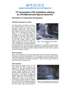
1 1VS Commodore LPG installation utilisingan LPG Memcal and Apexus of the components and operationLPG/Petrol changeover switchThe LPG change-over switch is mounted inthe instrument facia below the headlampcontrol, Apexus switch model PS105. Theswitch has illuminated indicators for Petrol and LPG . When the switch is in the LPG position the vehicle is operating on liquefiedpetroleum gas (LPG) Fig. operationThe vehicle will run on petrol when the switchis in the PETROL position and the Yellowindicator is lit. In this mode the LPG system is turned OFF and the vehicle functions in thesame way as a vehicle not fitted with LPG.
2 12 volts is applied to terminal A9 of the PowerTrain Control Module (PCM) from the LPG\PETROL changeover switch. The applicationof this voltage to the PCM causes it to operate the vehicle in petrol mode. The fuel gaugeshows the amount of petrol in the petrol operationWhen the Green indicator is lit the switch is in the Gas position and the engine managementcomputer (PCM) is operational in the LPG mode enabling the vehicle to run on LPG. Theoriginal dashboard fuel gauge shows the amount of LPG in the LPG cylinder when operatingin the LPG mode and the amount of petrol when operating on petrol Fig.
3 2. In the LPG modethe 12 volt signal wire to the PCM is removed and 12 volts is applied to the LPG MIXTURECONTROL COMPUTER and the LPG valves, via an electronic safety cut-out. This enablesthe vehicle PCM to operate the LPG system and provides power to the LPG MIXTURECONTROL COMPUTER to ensure closed loop control of fuel 1 Apexus PS105 Gas/Petrol mode Switch2 Injector Pulse widthIn all LPG operating modes, except enginecranking the petrol injector pulse width is setto zero. The PCM injects petrol duringcranking to assist starting. The amount ofpetrol delivered during the start, crank intervalis determined by the coolant temperature andthe crank time Fig.
4 3. After starting nofurther petrol is delivered to the Fuel PumpThe petrol fuel pump relay operates the petrolpump for about two seconds when the ignitionswitch is first turned on and continues tooperate during cranking During normalLPG operation the petrol pump is not runningunless engaged by the Timing MapA special Electronic Spark Timing (EST) mapwhich has been programmed to provideoptimum timing for LPG operation and isbuilt into the Memcal PROM (ProgrammableRead Only Memory).Should the engine speed drop below 300 RPMthe spark plugs are prevented from firing toreduce the risk of backfiring in the air ComputerFor vehicles fitted with a trip computer thePCM fuel usage output signal has a modifiedcalibration to suit LPG Memcals are installed/removed bydisconnecting the battery from the vehicle.
5 Removing the top cover on the PCM modulelocated in the left hand kick panel of thevehicle and then pulling outwards the twolocking tabs retaining the Memcal in 2 Dash Fuel Gauge used for LPG and 3 Petrol Injectors 4 Petrol Pump 5 Memcal Location LPG Memcal is then substituted for thePetrol Memcal in the polarised connector andthe locking tabs and cover replaced Fig. 5 andFig. PROM (Programmable Read OnlyMemory) contained within the LPG Memcalhas been programmed so that the PCM canoperate in one of two modes, either Petrol or LPG .Which mode the PCM is operating in isdetermined by whether or not there is 12 voltson terminal A9 of the Commodores with a PCM barcodenumber where the 9th, 10th, 11th and 12thdigit make a number less than 5111 or if the8th digit is not a 5 will require a new servicePCM.
6 This item may be ordered from anauthorised parts outlet. Please note thebarcode number is the important number onthe PCM label for determining LPG operation and the Service Number, or Memcal detailsmay differ from vehicle to the correct VS Memcal to install into the Powertrain Control Module (PCM). TheTypecode number on the LPG Memcal needs to be InstallationFit, tank, LPG (Liquefied Petroleum Gas)lines, converter, mixer, water lines, vapourline, vapour control valve, filler system, lock-offs and any other hardware required for theparticular installation . The engine bay LPGlock-off (solenoid valve) and the vaporiser(converter) must be fitted close to the LHS(Left Hand Side) spring tower Fig.
7 InstallationPreparation before fitting loomRemove the LHS and RHS (Right Hand Side)kick panel revealing the PCM (Powerline Control Module) on the LHS and wiring loom onthe RHS (Right Hand Side). Remove the cover panel under the steering wheel and the glove-Fig. 6 Fitting a 7 Identifying Memcal 8 Vapouriser, Lockoff and the ApexusElectronic Safety cut-out (Model CO100), whichprovides short circuit and overload protectionwithout blowing the The PCM module is removed from itsplastic carriage by releasing the clips andsliding outwards. Unplug the three connectorsfrom the end of the PCM and remove from PCM wiring loom has a sub-loom plugabout 300mm from the PCM connectors,disconnect this plug Fig.
8 17. By pressing thethree latches on the large firewall grommetlocated inside of the vehicle LHS release thegrommet and pull the PCM loom into theengine bay. Using a sharp knife carefully slicethe rubber grommet at the ends of the plasticclip and remove from the vehicle loom Fig. the sharp knife remove enough rubberfrom the inside of the grommet to allow the LPG loom (engine bay section) and the mixturecontrol valve wiring to fit without over expanding the the cover on the engine bay fuse box located near the battery and lift up the relay andfuse support container after using a screwdriver to release the two latches on the top surfaceof the relay bar revealing the wiring to the installation engine bayFit a changeover relay into the spare locationin the engine relay box on the support barmarked HORN THEFT and mark thelocation using the sticker provided LPG(Petrol Pump Isolate) Fig.
9 10. If this locationis not available fit the relay nearby and markthe relay with the sticker. Cut the Violet wirewhich goes to terminal 87a of the relaymarked F/PUMP about 200mm from therelay. This Violet wire is from the oilpressure switch via a connector in the the engine bay part of the LPG loomthrough the grommet hole opened in thepreceding paragraphs. Lay the LPG loomaround the engine bay with other vehiclewiring crossing the front of the vehicle bytucking it under the radiator sealing strips Neatly feed the end of the LPG loom intothe relay box and crimp the two Orange wirescoming from the LPG loom about 300mmbefore the end onto the Orange wires from thefuel pump relay exposed above Fig.
10 11. Theorder of these wire is not important. Connectthe four receptacles at the end of theLPG loom to the petrol pump isolate relayfitted above. Terminals 30 and 87a of theFig. 9 Firewall Grommet 10 Engine Bay Relay Box showing Fuel PumpIsolation Relay preferred 11 Relay Bar removed from mount showingIsolation go to the Orange wires (any order).Black is connected to 85 and Pink to 86 . Tuckthe wires neatly into place to allow the relaybox to be refitted without jamming any wiresFig. 11. Next align the LPG engine loomsection so that the Brown Tacho wire locatedin the vehicle wiring loom to the rear of theLHS spring tower Fig.