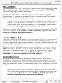
Transcription of VSIM (VEHICLE SYSTEM INTERFACE MODULE) USAGE …
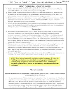
1 2015 Chassis Cab VSIM USAGE Instructions 09/01/2014 VSIM VSIM ( vehicle SYSTEM INTERFACE module ) USAGE INSTRUCTIONS Overview: The RAM Truck engineered upfitter module called the VSIM ( vehicle SYSTEM INTERFACE module ) with sales code XXS is standard with Ambulance Prep (sales code AH2), a must have option with PTO Prep (sales codes LBN or LBV), and is available as a stand-alone option. It provides a multitude of useful I/O s to increase upfitter friendliness and upfit simplification. Vehicles not ordered with this option from the factory cannot be retrofitted.
2 Specifics supplied below: 1. Ghost drawings showing the module location within the dash panel. 2. The VSIM includes an upfitter wire harness kit (part number 68211680AA or 68211680AB) consisting of four separate color coded harness bundles. Each individual color harness must only be plugged into its corresponding VSIM connector cavity, see photos below showing harness color installations. 3. A photo of the four individual color coded VSIM upfitter harness bundles. Note that in a few instances an individual wire color is duplicated within a bundle these duplications are further identified with a paper flag showing its circuit number.
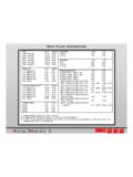
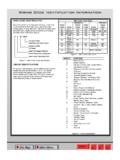
3 It s recommended that the upfitter, upon harness bundle routing direction determination(s), install additional harness bundle abrasion protection over each bundle (such as harness convolute). 4. Photos showing module installation within a vehicle and harness bundles. 5. A chart below delineates the circuits within each color harness bundle, circuit number, signal, wire insulation colors, maximum allowable amperage per circuit, and circuit function. 6. A chart below delineates the available 125 kbaud CAN bus messages. If downloadable DBC files are needed, they should be requested via the website 7.
4 Note 3: PTO idle speed circuits W541, W542, W543 can only be programmed to function if the vehicle was built with PTO option sales codes LBN or LBV. VSIM Blunt cut and heat shrunk insulations; to be cut off as necessary Duplicate wire color circuit # tag 2015 Chassis Cab VSIM USAGE Instructions 09/01/2014 VSIM GREY HARNESS GREEN HARNESS BROWN HARNESS BLACK HARNESS 2015 Chassis Cab VSIM USAGE Instructions 09/01/2014 GREY HARNESS GREEN HARNESS BROWN HARNESS BLACK HARNESS Note: When inserting the VSIM harness connectors an audible click will be heard when the connector is fully seated.
5 2015 Chassis Cab VSIM USAGE Instructions 09/01/2014 2015 Chassis Cab VSIM USAGE Instructions 09/01/2014 2015 Chassis Cab VSIM USAGE Instructions 09/01/2014 2015 Chassis Cab VSIM USAGE Instructions 09/01/2014 2015 Chassis Cab VSIM USAGE Instructions 09/01/2014 2015 Chassis Cab VSIM USAGE Instructions 09/01/2014 2015 Chassis Cab VSIM USAGE Instructions 09/01/2014