Transcription of Water Electrolysis: Status and Potential for Development
1 Fraunhofer ISE Water Electrolysis: Status and Potential for DevelopmentTom SmolinkaFraunhofer-Institut f r Solare Energiesysteme ISEJ oint NOW GmbH FCH JUWater Electrolysis DayBrussels (BE), April 03, 2014 Fraunhofer ISE 2 Agenda Short introduction to Fraunhofer ISE Applications for Water electrolysis Key features of different EL approaches Alkaline electrolysis - AEL PEM electrolysis - PEMEL High temperature electrolysis - HTEL Discussion of technical challenges: Performance and efficiency High pressure operation Part-load and overload capability Life-time R&D demand and summary Fraunhofer ISE 3 Fraunhofer Institute for Solar Energy Systems ISE Performing Research for the Energy Transition Energy Efficient Buildings Silicon Photovoltaics III-V and Concentrator Photovoltaics Dye, Organic and Novel Solar Cells Photovoltaic Modules and Power Plants Solar Thermal Technology Hydrogen and Fuel Cell Technology System Integration and Grids Electricity, Heat, Gas Energy Efficient Power Electronics Zero-Emission Mobility Storage Technologies Energy System AnalysisPhotos Fraunhofer ISE12 Business Areas.
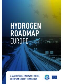
2 Fraunhofer ISE 4 Publicly accessible refueling station, located at premises of Fraunhofer ISE Main components of the filing station: (Membran electrolyser(30 bar / 6 Nm /h) Mechanical compressor Storage tanks Dispenser units (200/350/700bar) Filling according to SAE J2600 Integrated container solution Coupled with renewable energies: Photovoltaic modules (roof) Certified green electricity Two fuel cell cars from DaimlerH2 Refueling Station at Fraunhofer ISE Daimler Fraunhofer ISE 5 Hydrogen Production by Electrolytical Water SplittingKnown for more than 200 years. Invention of voltaic pile (1799) enabled investigations of electrolytic approaches Main principle demonstrated around 1800 by J.)
3 W. Ritter, William Nicholson and Anthony Carlise Today 3 technologies available: Alkaline electrolysis (AEL) Electrolysis in acid environment(PEM electrolysis - PEMEL)(SPE Water electrolysis) Steam electrolysis(High temperature electrolysis -HTEL or SOEL) Johann Wilhelm Ritter (1776-1810) Test set-up of RitterPicture credits: all electrolyser around 19002 H2O 2 H2+ O2 Fraunhofer ISE 6 Hydrogen Production by Electrolytical Water SplittingToday's industrial hydrogen production. Global hydrogen production:600 Bill. Nm /yr Mostly steam reforming Less than 1 % by Water electrolysisSource: DWV brochure (2006 )Industrial applicationTypical size electrolyserJewellery, laboratory and medical engineering5 - 500 Nl/hGenerator cooling in power plants5 - 20 Nm /hFeed Water Inertisation(BWR Water chemistry)10 - 50 Nm /hFloat glas production(protective atmosphere)50 - 150 Nm /h Electronics industry100 - 400 Nm /hMetallurgy 200 - 750 Nm /hFood industry (fat hardening) 100 - 900 Nm /hMilitary und aerospace< 15 Nm /h Fraunhofer ISE 7 Coupling Renewable Energies and Water ElectrolysisNew market opportunies with power to gas (PtG).
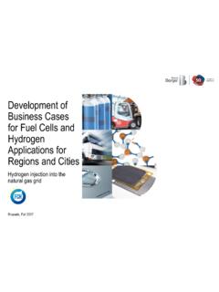
4 Power GenerationStorage and DistributionApplicationNuclearFossilWind SolarHydroBiomassResidentialIndustrialMo bilityPower GenerationH2 HeatPowerCGH2 / LH2 TrailerHydrogen StorageH2 ElectrolysisMethanisationLH2 HydrogenPipelineNatural Gas GridCO2 BufferNaturalGasStorageElectrical GridCO2 ElectricityH2OO2H2O2+-H2CH4H2OH2H2CH4 CNG Fraunhofer ISE (2013 06) Fraunhofer ISE 8 Coupling Renewable Energies and Water ElectrolysisNew market opportunies and .. New tasks for electrolysers in the PtG concept Operating (spinning) reserve for electrical grid (demand site management, load balancing) Hydrogen production as fuel for FCEV Large-scale storage systems by gas injection to the NG grid or underground storage Hydrogen for industrial applications Fraunhofer ISE 9 Coupling Renewable Energies and Water ElectrolysisNew market opportunies and new challenges.
5 Large EL plants up to x 100MW Scale-up vs. numbering up Optimum pressure level Small footprint for on-site H2 production Compact design High-pressure operation Highly flexible operation Fast start/stop cycling Efficient part-load operation and efficient stand-by mode Overload capability Decrease in CAPEX due to less annual full-load hours cost pressure!Definition H2 fueling stationsH2 fuelingcapacityRequiredEL sizeHRS Type XS80 kg/d~ 40 Nm /hHRS Type S212 kg/d ~ 100 Nm /hHRS Type M420 kg/d ~ 200 Nm /hHRS Type kg/d ~ 450 Nm /h75 MW AEL module, concept EdF (30 bar, 160 C) [1][1]LeRoy 1983, Int. J. Hydrogen Energy)Definition of HRS size according to H2 Mobility (2012) Fraunhofer ISE 10 Water ElectrolysisThree approaches for hydrogen and oxygen productionTechnologyTe m p.
6 RangeCathodic Reaction (HER)Charge CarrierAnodic Reaction (OER)Alkalineelectrolysis40 - 90 COH-Membrane electrolysis20 - 100 CH+High temp. electrolysis700 -1000 CO2- OHHeOH22222 eOHOOH222221222 HeH eHOOH222212 2222 OHeOH eOO22212 AELPEMELHTEL Fraunhofer ISE 11 Water ElectrolysisMain technical features - overviewAlkaline ElectrolysisMembrane ElectrolysisSolid Oxide ElectrolysisElectrolyte Liquid alkaline KOHS olid acid polymerCeramic metal compoundElectrodes Ni/Fe electrodes (Raney)Noble metals (Pt, Ir, ..)Ni doped ceramicTemperature 50-80 CRT - 90 C700 - 1,000 CPressure < 30 bar< 200 size(commercial)Max. 760 Nm H2/h~ MWelMax. 30 Nm H2/h~ 170 kWel~ 1 Nm H2/hkW rangeAELPEMELHTEL Fraunhofer ISE 12 Development Trends in Water Electrolysis(Pressurised) alkaline electrolysers (re)enter the MW classIHT (CH)H2 Nitidor (IT)McPhy - Enertrag (DE)Next Hydrogen (CA)NEL Hydrogen (NO)Suzhou Yingli Hydrogen (CN) Fraunhofer ISE 13 Development Trends in Water ElectrolysisPEM electrolysers entering MW class as OnSite (US)Hydrogenics (CA)Siemens (DE)ITM Power (GB)CETH2 (FR) Fraunhofer ISE 14(1) Performance and Efficiency of Water ElectrolysisComparison of different EL technologies at stack AELPEMELHTELT odayFuture Polarisation (V/i) curves with normalised current Fraunhofer ISE 15(1)
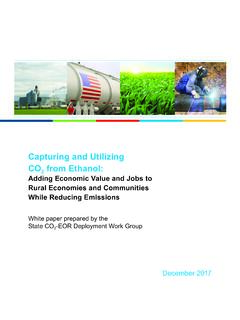
7 Performance and Efficiency of Water ElectrolysisAttempt to compare the efficiency at system level. Specific energy consumption as mea-sure for efficiency Manufacturer's data No standardised data Differernt pressure and H2purity Specifications for steady state operation 2,03,04,05,06,07,08,09,010,00,0100,1001, 00010,000100,0001000,000 Wasserstoffproduktionsrate [Nm /h]Spez. Energieverbrauch [kWh/Nm H2]AEL (atmosph risch)AEL (Druck)PEMEL StackPEMEL SystemThermodynamik @ STP Fraunhofer ISEH ydrogen Production Rate [Nm /h]Spec. Energy Demand[kWhel / Nm H2](atmospheric)(pressurised) Fraunhofer ISE 16 Energy consumption will not be reduced significantly in the future Higher operating pressure High power densities due to cost pressure Dynamic operation (start/stop, stand-by) 2,03,04,05,06,07,08,09,010,00,0100,1001, 00010,000100,0001000,000 Wasserstoffproduktionsrate [Nm /h]Spez.
8 Energieverbrauch [kWh/Nm H2]AEL (atmosph risch)AEL (Druck)PEMEL StackPEMEL SystemThermodynamik @ STP Fraunhofer ISEAELPEMEL(1) Performance and Efficiency of Water ElectrolysisAttempt to compare the efficiency at system level. Hydrogen Production Rate [Nm /h]Spec. Energy Demand[kWhel/ Nm H2](atmospheric)(pressurised)Thermodynam ics @ NTP Fraunhofer ISE 17(2) Do We Need High-Pressure Electrolysis?PEM electrolysis favours high pressure operation. Statoil HTHTEL compartment 30 bar AEL stack in pressure compartmentPressure [bar]AELPEMELHTELT ypically4 - (Atm.)Demonstrated~ 345~ 400(10) AEL (with liquid electrolyte) Pressure balanced design and complex system layout limit HP operation (CAPEX) PEMEL Differential pressure system, simpler layout and compact design favour HP operation HTEL Restrictions due to HT and HP in parallel DTU Giner55 bar PEM stack Fraunhofer ISE 18(2) Do We Need High-Pressure Electrolysis?
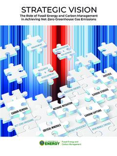
9 Typical pressure level of different applicationsH2 refueling stations (750 - 950 bar)Fueling of CGH2 trailer (up to 450 bar) Underground storage (200 - 300 bar)Pipelines (transportation: 60 - 80 bar)Methanisation (30 bar)Chemical industry (10 - 60 bar)Pipelines (local distribution: 1 - 4 bar) Water electrolysis: H2O H2+ O2 Statoil HT103[bar]102101100 PressurePiston compressorAEL stack in pressure compartmentElectrochemical compressionMechanical compressor Fraunhofer ISE 19(2) Do We Need High-Pressure Electrolysis?Electrochemical compression should be the first step! Statoil HTPiston compressorAEL stack in pressure compartment Hydrogen needs to be compressed for nearly all applications electrochemical compression is more efficient mechanical compression is cheaper at higher P Operating pressure of electrolyser is an economical trade-off (CAPEX) today: typically 10 - 40 bar In the future: probably up to 60 - 80 bar Higher pressures only for niche applications Large-scale storage and hydrogen mobility requires mechanical compressors Fraunhofer ISE 20(3) Part-load and Overload CapabilityModularity enables different applications.
10 Decentralised system 4 stacks MW -> MW Approx. 2,000 Nm /h H2 Centralised system 248 stacks MW -> 578 MW Approx. 120,000 Nm /h H2 Source: Fell - NEL Hydrogen, 2011, NOW-Workshop Berlin550 x 350 m Fraunhofer ISE 21(3) Part-load and Overload CapabilityMulti-stack configuration facilitates low part-load limit. Lower part-load limit is defined by Self-consumption of the EL system Gas purity H2in O2(quality and safety issue) New applications in energy sector (PtG) Multi-stack configuration for larger installations part-load non-critical H2 refueling stations with on-site electrolyser capacity small enough for system with single stack H2 demand and buffer tank allows nearly constant operation Fraunhofer ISE 22(3) Part-load and Overload CapabilityHigh overload could make sence.