Transcription of Water Hammer - KSB
1 KSB Know-how, Volume 1 Water HammerTable of ContentsPage1 Introduction ..32 General - The Problem of Water Hammer .. and Unsteady Flow in a Pipeline ..43 Water Hammer .. of Fluid and Pipe Wall .. 104 The Joukowsky Equation .. of the Joukowsky Equation ..125 Numerical Simulation of Water Hammer .. of Numerical Surge Analysis .. Acting on Pipelines as a Result of Water Hammer ..166 Computerised Surge Analysis .. Procedure .. between Ordering Party and Surge Analyst ..177 Advantages of Rules of Thumb and Manual Calculations .188 Main Types of Surge Control .. Storage .. Air Vessels .. Standpipes, One-Way Surge Tanks .. Flywheels .. valves .. valves .. Check valves .
2 249 Case Studies .. Study: Long-Distance Water Supply System .. Study: Stormwater Conveyance Pipeline ..26 Model Parameters ..26 Calculation of Actual Duty Data, First Results ..27 Surge Control Measures ..2810 Additional Literature ..30 Authors ..301 Contents1 IntroductionMost engineers involved in theplanning of pumping systemsare familiar with the terms hy-draulic transient , surge pres-sure or, in Water applications, Water Hammer . The questionas to whether a transient flow orsurge analysis is necessary dur-ing the planning phase or not isless readily answered. Under un-favourable circumstances, dam-age due to Water Hammer mayoccur in pipelines measuringmore than one hundred metresand conveying only severaltenths of a litre per second.
3 Buteven very short, unsupportedpipelines in pumping stationscan be damaged by resonantvibrations if they are notproperly anchored. By contrast,the phenomenon is not verycommon in building servicessystems, in heating anddrinking Water supply pipelines,which typically are short inlength and have a small cross-section. The owners or operators of sys-tems affected by Water hammerare usually reluctant to pass oninformation about any surgedamage suffered. But studyingthe photos taken of some acci-dents (Figs. 1-a, 1-b, 1-c)onething is clear: the damage causedby Water Hammer by far exceedsthe cost of preventive analysisand surge control measures. The ability to provide reliablydesigned surge control equip-ment, such as an air vessel oraccumulator1, flywheel and airvalve, has long been state of theart.
4 The technical instructionleaflet W 303 Dynamic Pres-sure Changes in Water SupplySystems published by the Ger-man Association of the Gas andWater Sector clearly states thatpressure transients have to beconsidered when designing andoperating Water supply systems,because they can cause extensivedamage. This means that a surgeanalysis to industry standardshas to be performed for everyhydraulic piping system at riskfrom Water Hammer . Dedicatedsoftware is available for thispurpose an important tool forthe specialist surge analyst touse. Consultants and systemdesigners are faced with thefollowing questions, which wehope to answer in this brochure: How can we know whetherthere is a risk of Water ham-mer or not?
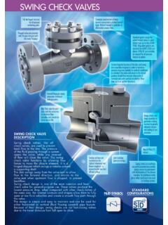
5 How significant are approxi-mation formulas for calculat-ing Water Hammer ? Can the surge analysis of onepiping system be used as abasis for drawing conclusionsfor similar systems? Which parameters are requiredfor a surge analysis? What does a surge analysiscost? How reliable is the surge con-trol equipment available andhow much does it cost to ope-rate it? How reliable is a computerisedanalysis? System designer and surgeanalyst have to work togetherclosely to save time and Hammer is a complexphenomenon; the purpose ofthis brochure is to impart abasic knowledge of its manyaspects without oversimplifyingthem. 31 Introduction1 Air vessels, sometimes also called accumulators , store potential energy by accumulating a quantity of pressurised hydraulic fluid in a suitableenclosed 1-c: DN 800 check valvefollowing a pressure surge in thedischarge pipeFig.
6 1-b: Destroyed support(double T profile 200 mm, per-manently deformed)Fig. 1-a: Completely destroyedDN 600 discharge pipe (wallthickness 12 mm)2 General The problem ofwater Steady and unsteady flowin a pipeline When discussing the pressure ofa fluid, a distinction has to bemade between pressure aboveatmospheric [p bar], absolutepressure [p bar(a)] and pressurehead h [m]. Pressure head h de-notes the height of a homogene-ous liquid column which gener-ates a certain pressure p. Valuesfor h are always referred to adatum, ( mean sea level, axi-al centreline of pipe and pipecrown etc.). As a rule, system designers startby determining the steady-stateoperating pressures and volumerates of flow.
7 In this context, theterm steady2means that volumerates of flow, pressures andpump speeds do not change withtime. Fig. a typicalsteady flow profile: With a constant pipe diameterand a constant surface rough-ness of the pipe s inner walls, thepressure head curve will be astraight line. In simple cases, apump s steady-state operatingpoint can be determined graphi-cally. This is done by determin-ing the point where the pumpcurve intersects the piping cha-racteristic. A pumping system can never beoperated in steady-state conditionall the time, since starting up andstopping the pump alone willchange the duty speaking, every changein operating conditions and everydisturbance cause pressure andflow variations or, put differently,cause the flow conditions tochange with time.
8 Flow condi-tions of this kind are commonlyreferred to as unsteady ortransient. Referring specifically topressures, they are sometimescalled dynamic pressure changesor pressure transients. The maincauses of transient flowconditions are: Pump trip as a result ofswitching off the power supplyor a power failure. Starting or stopping up one ormore pumps whilst otherpumps are in operation. Closing or opening of shut-offvalves in the piping system. Excitation of resonant vibra-tions by pumps with an un-stable H/Q curve. Variations of the inlet serve as a repre-sentative example showing thepressure envelope3with andwithout an air vessel followingpump The Problem of Water Hammer2 Not to be confused with the term static.
9 3 The term pressure envelope refers to the area defined by the minimum and maximum head curves along the fixed datum line resulting from alldynamic pressures occurring within the time period under review. Kote mstation re Druckh henlinieL ngehNN+mhmFig. : Steady-state pressure head curve of a pumping systemSteady-state pressure head curveMetres above sea levelLength700600500400300200 Metres above sea level [m]5001000150020002500 Length of pipe [m]0 Elevation of pipehmax PN Pipehmax WKhmin WKhsteadyhminhsteadyin Fig. the steady-state pressure head curve. Pressu-re head envelopes hminWKandhmaxWKwere obtained from an in-stallation with, hminand hmaxfrom an installation without airvessel. Whereas hminWKandhmaxWKare within the permissiblepressure range, hmingives evi-dence of vapour pressure (macro-cavitation) over a pipe distancefrom 0 m to approximately 800 m.
10 Almost across the entirelength of the pipe, the value ofhmaxexceeds the maximum per-missible nominal pressure of thepipe PN 16 (curve marked PNpipe ) and is, therefore, inadmis-sibly high. As a rule, vapourpressure is a most undesirablephenomenon. It can have the fol-lowing harmful effects: Dents in or buckling of thin-walled steel pipes and plastictubes. Disintegration of the pipe scement lining. Dirty Water being drawn intodrinking Water pipelinesthrough leaking connectingsockets. We will come back to the sub-ject of macro-cavitation, column separation, insection The Problem of Water HammerFig. : Pressure head envelope of pressure transients following pump tripPipe length L:2624 mInside diameter of pipe mmSteady-state flow rate:500 l/s Hpump mHoutlet:400 mAir vessel inlet pipe with a bypass and a non-return valve: Vair= m3, Vwater= m33 Water hammerPressure transients are also re-ferred to as surge pressure or, ifreferring to Water systems, waterhammer.