Transcription of Water Source Heat Pump Axiom Horizontal/Vertical …
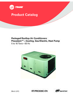
1 Product Catalog Water Source heat Pump Axiom Horizontal/Vertical GEH/GEV. 6 25 Tons 60 Hz November 2013 WSHP-PRC016D-EN. Introduction The 6 through 25 ton horizontal and vertical Water - Source heat pump is used in a broad range of applications. Schools, office buildings, health care/rehabilitation facilities, condominiums and retirement facilities are just a few of the types of buildings utilizing the energy conscious Water - Source design. Model GEH (pictured below) is a ceiling hung product that provides a serviceability to maintenance components; indoor air quality standards; sound attenuation; and best of all, higher efficiencies rated in accordance to ARI-ISO 13256-1 performance and ASHRAE standards. trane 's design incorporates system advantages such as Superior maintenance accessibility Dual circuit design Dual-sloped, plastic drain pan High and low pressure safeties as standard Maximum return-air and supply-air flexibility Dehumidification option Multiple fan speed motor packages Waterside economizing option Quiet unit design Supplemental electric heat option Integrated controls 1.
2 Fan Blower Section 2. Co-axial heat Exchanger 3. Water Connections 4. Thermal Expansion Valve 4 6 5. Dual Compressor 3. 2. 6. Low Voltage 1 8. 7. High Voltage 8. Integrated Controls 9. Hanging Rails 5. 3. 7. 9. Trademarks Axiom , ReliaTel,TOPSS,Tracer, trane , and theTrane logo are trademarks or registered trademarks ofTrane in the United States and other is a business of Ingersoll Rand. All trademarks referenced in this document are the trademarks of their respective owners. LonTalk is a registered trademark of Echelon Corporation. BACnet is a registered trademarks. All trademarks referenced in this document are the trademarks of their respective owners. Revision Summary WSHP-PRC016D-EN (16 November 2013). Added BACnet . 2013 trane All rights reserved WSHP-PRC016D-EN. Table of Contents Introduction .. 2. Features and Benefits.
3 4. Cabinet Description .. 4. Airflow Combinations .. 4. How it Works .. 7. Application Considerations .. 10. Model Number Description .. 13. General Data .. 14. Performance Data .. 16. Fan Performance Data .. 44. Waterside Economizer Performance Data .. 65. Electrical Data .. 67. Dimensional Data .. 73. Weights .. 97. Controls .. 98. Deluxe 24V features include: .. 98. Tracer UC400 / ZN524 functions include: .. 100. Dimensions .. 104. Specifications .. 104. Wireless Receiver/Wireless Zone Sensor .. 105. Specifications .. 105. Thermostats and Zone Sensors .. 107. Accessories .. 109. Control Wiring .. 111. Mechanical Specifications .. 114. WSHP-PRC016D-EN 3. Features and Benefits Cabinet Description The cabinet design incorporates sturdy (non-painted) galvanized metal for maximum durability and corrosive resistive equipment offers superior installation flexibility with service accessibility.
4 The cabinet front allows service access for the horizontal and vertical design offers four product variations of return-air and supply-air combinations. All combinations are order specific and may not be modified at the job site. See Figure 1, p. 4 for airside combinations. Hanging the horizontal configuration is accomplished through the robust metal stiffeners located beneath the unit. Optional vibration isolators are available to help decrease sound vibration during equipment operation. Airflow Combinations Figure 1. GEH airflow options (left), GEV airflow options (right). The 6 15 ton horizontal The sleek, narrow cabinet of SUPPLY-AIR. Control Box BACK SUPPLY-AIR. cabinet airflow flexibility the 6 25 ton vertical cabinet is BACK. 1. includes the following 1 designed to fit through a LEFT RETURN-AIR. combinations to aid in standard 36 in.
5 Doorway for RIGHT. SUPPLY-AIR applications where the FRONT RETURN-AIR installation during new or equipment is required to hug retrofit Control Box 2 2 TOP. a corridor or wall. SUPPLY equipment is available in four The four configurations are: supply-air/return-air LEFT RETURN-AIR. RIGHT RETURN-AIR. FRONT RETURN-AIR 1. Left return-air with back BACK RETURN-AIR. combinations are order 3. supply-air combination specific via the unit model SUPPLY-AIR. Control Box BACK. 3 number. 2. Left return-air with right RIGHT RETURN-AIR. supply-air combination FRONT SUPPLY-AIR. The four configurations are: BACK RETURN-AIR. 3. Right return-air with back 1. Front return-air with back 4 supply-air combination Control Box 4 TOP. SUPPLY. supply-air combination LEFT. 4. Right return-air with left 2. Front return-air with top SUPPLY-AIR. supply-air combination supply-air combination 3.
6 Back return-air with front supply-air combination Back return-air with top supply-air combination Access Panels The upper panels of the 12 25 ton verticals feature a key hole hanging design for ease of maintenance of the unit, allowing the panel to be hooked into place when attaching the panel to the unit. The panels are also sealed with a rubber gasket at all four edges to help eliminate air from escaping around the panel edge.. 4 WSHP-PRC016D-EN. Features and Benefits Air-side filter The air-side filter incorporates a 1-inch thick (nominal) or 2-inch thick (nominal), MERV 8 or MERV. 13 disposable fiberglass filters include an average synthetic dust weight arrestance of approximately 75%.This dust holding capability includes a colorless, odorless adhesive to retain dirt particles within the filter media after fiber contact.
7 Blower housing The blower housing is constructed of non-corrosive galvanized steel. It is a double wide/double inlet, forward curved wheel moved by an integral horsepower motor with sealed bearings. Cabinet insulation The cabinet insulation design meets UL 181 air-stream surface of the insulation is fabricated of a non-biodegradable Source . Compressor Dual circuit designs of the GEH and GEV models feature scroll compressors are highly efficient and incorporate external vibration isolators and thermal overload protection. Co-axial Water -to-Refrigerant Coil The unit's internal heat exchanging Water coil is engineered for maximum heat transfer. The copper or cupro-nickel seamless tubing is a tube within a tube inner- Water tube contains a deep fluted curve to enhance heat transfer and minimize fouling and scaling. It is available in either copper or cupro-nickel (selectable option).
8 Outer refrigerant gas tube is made from steel material. The coil is leak tested to assure there is no cross leakage between the Water tube and the refrigerant gas (steel tube) coil. Co-axial heat exchangers are more tolerant to freeze rupture. Drain pan The unit drain pan is composed of plastic, corrosive resistive pan is positively sloped to comply with ASHRAE 62 for indoor air quality (IAQ) conformity. Access to the drain pan is provided through two access panels for cleaning purposes for all models. Expansion Valve The refrigerant flow metering is made through the thermal expansion valve (TXV). It allows the unit to operate with an entering fluid temperature from 25 F to 120 F and entering air temperatures from 55 F to 85 valve is designed to meter refrigerant flow through the circuitry to achieve desired heating or cooling.
9 Unlike cap-tube assemblies, the expansion valve device allows the exact amount of refrigerant required to meet the coil load precise metering by theTXV increases the efficiency of the unit. Hanging device The hanging channel for the horizontal unit runs the length of the structural integrity of the design helps ensure that bracket deflection or unit bowing does not occur as a result of the weight of the unit. WSHP-PRC016D-EN 5. Features and Benefits Isolation for the hanging bracket is provided with a rubber grommet design as an isolation device helps prevent sound vibration from reaching the structural support members of the building during compressor start and stop. Refrigeration piping Unit copper tubing is created from a 99% pure copper formation that conforms to the American Society ofTesting Materials (ASTM) B743 for seamless, light-annealed processing.
10 The unit's copper refrigeration system is designed to be free from contaminants and conditions such as drilling fragments, dirt, or excludes the possibility of these contaminants from damaging the compressor motor. Reversing valve A system reversing valve (4-way valve) is included with all heating/. cooling valve is piped to be energized in the cooling mode to allow the system to provide heat if valve failure were to occur. Once the valve is energized for cooling, it will remain energized until the control system is turned to the OFF position, or a heating cycle is initiated. Water Connections Water hookups for the 6 25 ton units are located internal to the equipment to help alleviate damage to the Water copper during shipment or job storage of units prior to installation. Each unit 1. (although dual circuit) contains a single supply and return Water following figure provides large tonnage Water hook-up information for model GEV.