Transcription of WaveRunner GP1200R Service Manual
1 *LIT186160215* Service Manual LIT-18616-02-15F0X-28197-ZA-11 WaveRunner GP1200R E NOTICE This Manual has been prepared by the yamaha motor Company Ltd. primarily for use byYamaha dealers and their trained mechanics when performing maintenance procedures andrepairs to yamaha equipment. It has been written to suit the needs of persons who have abasic understanding of the mechanical and electrical concepts and procedures inherent in thework, for without such knowledge attempted repairs or Service to the equipment could renderit unsafe or unfit for the yamaha motor Company, Ltd.
2 Has a policy of continuously improving its prod-ucts, models may differ in detail from the descriptions and illustrations given in this publica-tion. Use only the latest edition of this Manual . Authorized yamaha dealers are notifiedperiodically of modifications and significant changes in specifications and procedures, andthese are incorporated in successive editions of this Manual . A10001-0* WaveRunner GP1200 RSERVICE Manual 2000 yamaha motor Co., Edition, February 2000 All rights part of this publication may be reproduced or transmitted in any form or by any means including photocopying and recording without the written permission of the copyright holder.
3 Such written permission must also be obtained before any part of this publication is stored in a retrieval system of any in USALIT-18616-02-15 E HOW TO USE THIS Manual Manual FORMAT All of the procedures in this Manual are organized in a sequential, step-by-step format. Theinformation has been compiled to provide the mechanic with an easy to read, handy refer-ence that contains comprehensive explanations of all disassembly, repair, assembly, andinspection this revised format, the condition of a faulty component will precede an arrow symbol and the course of action required will follow the symbol, , l BearingsPitting/scratches assist you in finding your way through this Manual , the section title and major heading isgiven at the top of every page.
4 ILLUSTRATIONS The illustrations within this Service Manual represent all of the designated models. CROSS REFERENCES The cross references have been kept to a minimum. Cross references will direct you to theappropriate section or chapter. E IMPORTANT INFORMATION In this Service Manual particularly important information is distinguished in the Safety Alert Symbol means ATTENTION! BECOME ALERT! YOUR SAFETY ISINVOLVED!WARNING Failure to follow WARNING instructions could result in severe injury or death to the machine operator, a bystander, or a person inspecting or repairing the water : A CAUTION indicates special precautions that must be taken to avoid damage to the water : A NOTE provides key information to make procedures easier or : This part has been subjected to change of specification during production.
5 E HOW TO USE THIS MANUAL1 To help identify parts and clarify procedure steps, there are exploded diagrams at the startof each removal and disassembly Numbers are given in the order of the jobs in the exploded Symbols indicate parts to be lubricated or replaced (see SYMBOLS ). 4 A job instruction chart accompanies the exploded diagram, providing the order of jobs,names of parts, notes in jobs, Dimension figures and the number of parts, are provided for fasteners that require a tight-ening :Bolt or screw size.
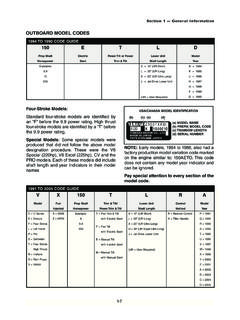
6 M10 (D) 25 mm (L) 6 Jobs requiring more information (such as special tools and technical data) are 25 mmDL E A50001-1-4 SYMBOLS Symbols 1 to 9 are designed as thumb-tabs to indicate the content of a General Information2 Specifications3 Periodic Inspection and Adjustment4 Fuel System 5 Power Unit6 Jet Pump Unit7 Electrical System8 Hull and Hood9 Trouble analysis Symbols 0 to E indicate specific data:0 Special toolA Specified liquidB Specified engine speedC Specified torqueD Specified measurementE Specified electrical value[Resistance ( ), Voltage (V), Electric current(A)] Symbol F to H in an exploded diagramindicate the grade of lubricant and the loca-tion of lubrication point.
7 F Apply YAMALUBE 2-W oilG Apply water resistant grease ( yamaha grease A, yamaha marine grease)H Apply molybdenum disulfide grease Symbols I to N in an exploded diagramindicate the grade of the sealing or lockingagent, and the location of the applicationpoint:I Apply Gasket Maker JApply Yamabond #4 ( yamaha bond number 4)KApply LOCTITE No. 271 (Red LOCTITE)LApply LOCTITE No. 242 (Blue LOCTITE)MApply LOCTITE No. 572 NApply silicone sealantNOTE:In this Manual , the above symbols may notbe used in every +ELECHULLHOODTRBLANLST INFORMATION1 SPECIFICATIONS2 SPECPERIODIC INSPECTION AND ADJUSTMENT3 FUEL SYSTEM4 FUELPOWER UNIT5 POWRJET PUMP UNIT6 JETPUMPELECTRICAL SYSTEM7 ELECHULL AND HOOD8 HULL HOODTROUBLE ANALYSIS9 GEN INFOINSP ADJ +TRBL ANLSA30000-0 E 1 GENINFO CHAPTER 1 GENERAL INFORMATION IDENTIFICATION NUMBERS.
8 1-1 PRIMARY 1-1 ENGINE SERIAL NUMBER .. 1-1 JET PUMP UNIT SERIAL NUMBER .. 1-1 HULL IDENTIFICATION NUMBER ( ).. 1-1 SAFETY WHILE WORKING .. 1-2 FIRE PREVENTION .. 1-2 OILS, GREASES AND SEALING 1-2 GOOD WORKING PRACTICES .. 1-3 DISASSEMBLY AND ASSEMBLY .. 1-4 SPECIAL TOOLS .. 1-5 MEASURING .. 1-5 REMOVAL AND INSTALLATION .. 1-6 1-1 EGENINFO IDENTIFICATION NUMBERS A60700-0* IDENTIFICATION NUMBERS PRIMARY NUMBER The primary number is stamped on alabel attached to the inside of the enginecompartment.
9 Starting primary number:F0X: 800101 ~ ENGINE SERIAL NUMBER The engine serial number is stamped on alabel attached to the cylinder head. Starting serial number:67X: 000101 ~ JET PUMP UNIT SERIAL NUMBER The jet pump unit serial number is stampedon a label attached to the intermediatehousing. Starting serial number:67X: 800101 ~ HULL IDENTIFICATION NUMBER ( ) The is stamped on a plate attached tothe aft deck. 1-2 EGENINFO SAFETY WHILE WORKING SAFETY WHILE WORKING The procedures given in this Manual arethose recommended by yamaha to be fol-lowed by yamaha dealers and theirmechanics.
10 FIRE PREVENTION Gasoline (petrol) is highly vapor is explosive if ignited. Do not smoke while handling gasoline(petrol) and keep it away from heat, sparks,and open flames. VENTILATION Petroleum vapor is heavier than air and isdeadly if inhaled in large quantities. Engineexhaust gases are harmful to test-running an engine indoors,maintain good ventilation. SELF-PROTECTION Protect your eyes with suitable safety spec-tacles or safety goggles when grinding ordoing any operation which may cause parti-cles to fly hands and feet by wearing safetygloves or protective shoes if appropriate tothe work you are doing.