Transcription of Wavetronix SmartSensor 125 HD User Guide - Signal Control
1 Wavetronix LLC380 South Technology CourtLindon, Utah 84042 SmartSensor HDUSER Guide 2008 Wavetronix LLC. All Rights HD, SmartSensor Manager HD, Click!, Wavetronix , and all associated logos are trademarks of Wavetronix LLC. All other product or brand names as they appear are trademarks or registered trademarks of their respective holders. Protected by Patent Nos. 6,556,916 and 6,693,557. Other and international patents Company shall not be liable for any errors contained herein or for any damages arising out of or related to this document or the information contained therein, even if the Company has been advised of the possibility of such document is intended for informational and instructional purposes only. The Company reserves the right to make changes in the specifications and other information contained in this document without prior Part 15 Compliance: This device complies with Part 15 of the Federal Communications Commission (FCC) rules which states that operation is subject to the following two conditions: (1) this device may not cause harmful interference, and (2) this device must accept any interference received, including interference that may cause undesirable operation.
2 FCC compliance statements for applicable optional modules are to be found in the module specifications. Unauthorized changes or modifications not expressly approved by the party responsible for compliance with the FCC rules could void the user s authority to operate this not shorten supplied cable less than manufacturer s recommended length. Sensor cable must be at least 2 m long to maintain FCC : The advertised detection accuracy of the company s sensors is based on both external and internal testing, as outlined in each product s specification document. Although our sensors are very accurate by industry standards, like all other sensor manufacturers we cannot guarantee perfection or assure that no errors will ever occur in any particular applications of our technology. Therefore, beyond the express Limited Warranty that accompanies each sensor sold by the company, we offer no additional representations, warranties, guarantees or remedies to our customers.
3 It is recommended that purchasers and integrators evaluate the accuracy of each sensor to determine the acceptable margin of error for each application within their particular system(s).7-21- 08 Contents Introduction 7 SmartSensor HD Package 7 Selecting a Mounting Location 8 Installing the SmartSensor HD Chapter 1 13 Selecting the Mounting Height 14 Attaching the Mount Bracket to the Pole 16 Attaching the Sensor to the Mount Bracket 16 Aligning the Sensor to the Roadway 17 Applying Silicon Dielectric Compound 18 Connecting the SmartSensor Cable 18 Connecting Power and Surge Protection Chapter 2 21 Connecting Lightning Surge Protection 21 Connecting AC Power Conversion 25 Connecting DC Power 28 Wiring Communication 30 Installing SmartSensor Manager HD Chapter 3 35 Installing SSMHD 35 Microsoft .NET Framework 38 Communication Chapter 4 41 Serial Connection 42 Modem Connection 43 Internet Connection 45 Virtual Connection 46 Troubleshooting Connections 48 Communication Protocol Type 49 Address Book 49 Viewing Connection Information 50 Uploading the Sensor s Embedded Software 51 Sensor Settings Chapter 5 55 General Tab 55 Comm Tab 56 Advanced Tab 57 Lane Setup Chapter 6 61 Sensor Alignment 62 Lane Configuration Automatic 63 Lane Configuration Manual 65 Lane Verification 69 Contents (cont.)
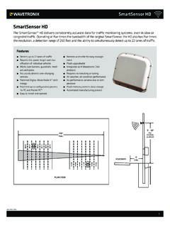
4 Data Setup & Collection Chapter 7 73 Interval Data 74 Per Vehicle Data 76 Loop Emulation 76 Data Storage & Download 77 Bin Definitions 81 Approaches 83 Date and Time 84 Data Push 85 Tools Chapter 8 89 Backup/Restore 89 Export Data 90 Contact Closure Communications Chapter 9 93 Selecting the Contact Closure Model 93 Programming Sensors for Use with Contact Closures 95 Programming Contact Closures 96 Appendix 99 Appendix A - SmartSensor HD Specifications 99 Appendix B - Cable Connector Definitions 100 Appendix C - Old Cable Connector Definitions 101 Appendix D - Cable Lengths 103 Appendix E - Direct Serial Connections 105In the IntroductionSmartSensor HD Package Selecting a Mounting Location The Wavetronix SmartSensor HD traffic sensor utilizes the latest technology to collect and deliver traffic statistics. The SmartSensor HD collects information through the use of a GHz (K band) operating radio frequency and is capable of measuring traffic volume and classification, average speed, individual vehicle speed, lane occupancy, and presence.
5 Classified as Frequency Modulated Continuous Wave (FMCW) radar, the SmartSensor HD detects and reports traffic conditions simultaneously over as many as ten lanes of traffic. Once SmartSensor HD is installed, the configuration process is quick and easy. After installation, this unit will require little or no on-site maintenance and can be remotely reconfigured for optimal performance. This installation Guide outlines the step-by-step process of installing and configuring the SmartSensor HD. Any questions about the information in this Guide should be directed to Wavetronix or your HD PackageA standard SmartSensor HD package contains the following items: SmartSensor HD SS125 detector with installed back-plate Sensor mounting kit Sensor cable SmartSensor Manager HD (SSMHD) software SmartSensor HD user Guide Introduction8 INTRODUCTION o SmartSensor HD user Guide Check the packing slip for actual contents. If any of these items are missing, note the serial number located on the back of the sensor and contact your products may be purchased through your distributor.
6 The following optional items are not included unless specifically ordered (check packing list for actual inventory):Click! 172/174 contact closure adapter Click! 200 surge protector Click! 201/202 AC to DC converter Click! 210 circuit breaker switch Click! 230 AC surge module Selecting a Mounting LocationConsider the following guidelines when selecting a mounting location:Lane Coverage Sensor mounting locations should be selected so that all monitored lanes are within 6 to 250 feet and run parallel with each other. Multiple sensors should be considered if more than 10 lanes need to be simultaneously monitored. If lanes do not need to be simultaneously monitored up to 22 lanes can be configured for collection by a single Lanes When the sensor is used to collect both mainline and ramp data, the pole position should be selected so that the on and off ramp lanes run parallel with the mainline. If lanes are not parallel, installation of multiple SmartSensor HD units should be considered to achieve the sensor s 2 degree side-to-side angle requirement.
7 Sensors on the Same Pole When multiple sensors are mounted on the same pole, they will not be subject to interference if they are configured to operate using different RF channels and are separated vertically by a few feet. The higher sensor would typically be used for the lanes further from the pole in order to minimize on Opposing Poles SmartSensor HD units facing each other on opposing poles should operate on different RF channels and be separated by 40-foot lateral offset, if The SmartSensor HD is designed to work accurately in the presence of barriers, but in general if there is an alternate mounting location that would avoid any type of structural occlusion, this is preferred. Avoid occlusion by trees, signs, and other roadside Structures and Parallel Walls For best performance, it is preferred that sensor locations have a 30-foot lateral separation from overhead sign bridges, overpasses, tunnels, parallel walls, and parallel-parked vehicles in order to avoid multiple reflection paths from a single o SmartSensor HD user Guide Portable (left) and Permanent (right) Sensor Stations Figure Mounting Height The mounting height should be based upon the offset from the lanes of interest.
8 For each offset, the minimum, maximum, and best range of heights is shown in Table , found in chapter 1. In general, the range of recommended heights is between 9 and 50 Offset The minimum recommended offset from the edge of the first lane of interest is 6 Locations Sensor sites on arterials or other roadway segments with regulated stop lines should be selected at mid-block positions to increase accuracy by avoiding positions at which vehicles are often stopped in front of the Locations SmartSensor HD is often used at permanent ATR (automatic traffic recorder) stations. The number of stations along a single roadway and the distance between stations should be selected to achieve adequate levels of statistical confidence. Permanent ATR stations, which are selected to cover interstate, principal arterial, and other national and state highways, are used to establish seasonal adjustment factors for count data from temporary collection sites (see Figure ).
9 Cable Lengths Ensure that you have sufficient homerun and sensor cabling. Cables can be as long as 600 feet if they re using 24 VDC operation and RS-485 communications; for longer connections, alternate wired and wireless options should be IInstalling the SmartSensor HDCHAPTER 1 - Installing the SmartSensor HDCHAPTER 2 - Connecting Power and Surge ProtectionInstalling the SmartSensor HD is quick and easy. Once installed, the SmartSensor HD configures automatically and requires little or no on-site maintenance. The installation process includes attaching the mounting bracket to the pole; attaching the sensor to the mounting bracket; aligning the sensor; applying a silicon dielectric compound to the sensor connector; and connecting the SmartSensor cable to the not attempt to service or repair this unit. This unit does not contain any components and/or parts serviceable in the field. Any attempt to open this unit, except as expressly written and directed by Wavetronix , will void the customer warranty.
10 Any visible damage to exterior seal labels will void the warranty. Wavetronix is not liable for any bodily harm or damage caused if unqualified persons attempt service or open the back cover of this unit. Refer all service questions to Wavetronix or an authorized this ChapterSelecting the Mounting Height Attaching the Mount Bracket to the Pole Attaching the Sensor to the Mount Bracket Aligning the Sensor to the Roadway Applying Silicon Dielectric Compound Connecting the SmartSensor Cable 1 Installing the SmartSensor HD14 CHAPTER 1 o INSTALLING THE SmartSensor HD CautionUse caution when installing any sensor on or around active roadways. Serious injury can result when installation is performed using methods that are not in accordance with authorized local safety policy and procedures. Always maintain an appropriate awareness of the traffic conditions and safety procedures as they relate to specific locations and the Mounting HeightAfter selecting a mounting location within the recommended range of offsets (see introduction and Figure ), use Table to select a mounting Mounting HeightFigure Offset from first Detection Lane (ft)Recommended Mounting Height (ft)Minimum Mounting Height (ft)Maximum Mounting Height (ft)