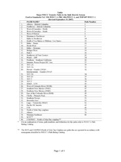
Transcription of WECC Power System Stabilizer Tuning Guidelines
1 WECC Power System Stabilizer Tuning GuidelinesForwardThis document is not intended to be a detailed Tuning procedure for a specific pieceof equipment. The intent is to meet the inter-area needs of WECC; local systemneeds may dictate additional requirements. It is intended for the experienced tuningengineer as the minimum criteria needed to tune a PSS. A detailed tuningprocedure should be developed for the specific PSS being tuned. This guideline ismeant to be an aid in the development of the Tuning basic intent of adding a Power System Stabilizer (PSS) is to enhance dampingto extend Power transfer limits. The very nature of a PSS limits its effectiveness tosmall excursions about a steady state operating point. The small excursions aboutan operating point are typically the result of an electrical System that is lightlydamped which can cause spontaneous growing oscillations, known as systemmodes of damping is required when a weak transmission condition exists along witha heavy transfer of load.
2 In the WECC, inter-area modes of oscillation occur and Hz. with the predominant mode at approximately PSS works in conjunction with the excitation System of a synchronous machine tomodify the torque angle of the shaft to increase damping. The performance of theexcitation System is critical in the overall capability of a PSS. Tuning of a PSS shallonly be accomplished after the excitation System has been tuned and new equipment, PSS may be software incorporated in digital automatic voltageregulators. AVR terminal voltage and current measurements are used to computeaccelerating Power and synthetic speed (integral of accelerating Power ). PSS costcan be low if PSS is required in competitive Power plant procurement specifications should include requirement for Tuning duringcommissioning and a requirement for stability program model and typically utilizes phase compensation and adjusting phase compensation is themain task in PSS Tuning .
3 Phase compensation is accomplished by adjusting the PSSto compensate for phase lags through the generator, excitation System , and powersystem such that PSS provides torque changes in phase with speed should be performed when System configurations and operating conditionsresult in the least damping. Verification should demonstrate that instability is notintroduced through normal operating ranges as well as expected of concernPSS benefits to the WECC System are significant, however, there is potential forequipment damage. Some areas of concern are: PSSs are manufactured as both analog and digital types. Testing methodsmay not be identical with both types of PSSs. PSS modification of torque angles by varying excitation can excite turbinegenerator shaft torsionals where shaft torsionals are less than 20 hertz. Thisis especially true for PSSs that utilize speed as input.
4 Typically torsional filtersare used to remove the torsional contribution to the input to the PSS. PSS output can interfere with transient response of excitation output limits are usually incorporated in the PSS scheme. PSS can interact with underexcitation limiters. Thus the limiters must betuned to work in conjunction with the PSS. Rapid load changes can result in large VAR swings from PSS response thatutilize electric Power . Upgrading to type 2 PSS input (integral of acceleratingpower) may solve this Input TypesPSS are designed with various types of inputs. They include speed, frequency, Power , accelerating Power and integral of accelerating Power . The PSS may derivethese quantities from generator terminal voltage and current practice is to digitally derive a synthetic speed measurement (integral ofaccelerating Power ) from generator terminal voltage and current TuningThe Tuning of PSS differs based on the type of input.
5 However, in general Tuning ofPSS consists of the following:Verifying the functionality of all aspects of the PSS includes the compensating features, limits, and protections. Allpotentiometers, if so equipped, should have smooth and continuous controlthroughout their Output LimiterSet output limits so that PSS cannot move generator terminal voltage beyonda predetermined value. Typical range of settings is from 5% to 10% ofrated generator terminal voltage. Asymmetrical limits may be and AlarmsPSS output protection should be coordinated with the output limiter. Since theoutput limiter provides a wider range of signals than can be tolerated insteady-state operation, several methods may be used to obtain security fromdriving the excitation System beyond the normal operating limits. Thesemethods include voltage-sensitive switches, auxiliary timing circuits andlimiter voltage sensitive switch usually measures generator terminal voltage anddisconnects the PSS signal from the excitation System when the terminalvoltage exceeds a preset limit.
6 The auxiliary timer method uses a circuit tomonitor the PSS output level, and if the level exceeds a preset limit for agiven time, the PSS signal is removed from the excitation protection removes the PSS from service an alarm should is an interrelationship between the phase compensation and thewashout time constant. Short washout time constants provide additionalphase compensation in frequency-based PSS at the lower frequencies whiledramatically reducing the washout time constant of 10 seconds or less is recommended to quicklyremove low frequency components (below Hz) from the PSS output. Thesmaller time constant will reduce the influence on the System voltage from thePSS during any sustained/extended frequency deviation ( , loss ofgeneration), especially if the PSS has a high gain CompensationIdentify inter-area modes of oscillation. Measure generator and excitationsystem response without PSS.
7 Tune PSS to provide as close to 0 degrees ofphase shift as possible at the inter-area frequency or local stability concerns require PSS settings resulting in an inter-area phaseshift other than zero, the setting shall in no case result in a phase shift inexcess of 30 degrees at inter-area PSS provides substantial phase shift so that the electrical torqueprovided by the generator is approximately in phase with speed. The goal isto eliminate phase lag as best as possible throughout a wide range offrequencies of interest, then adjust gain as outlined TestA gain as high as practicable is required for best contribution to systemdamping. Since the maximum gain that is safely usable depends upon manyfactors, it is best determined by test. The gain test shall be performed underoperating conditions that result in maximum overall System gain so that thetrue gain margin is identified.
8 Generally, this occurs with the unit loaded to atleast 80% of full load. If shaft torsionals are of concern, the torsionals shall bemonitored during the gain test for the maximum safely usable gain may be made with the PSS fullyoperative and either PSS output, field voltage, or generator terminal voltagedeviation being recorded, by slowly advancing the gain until a small rapidoscillation, usually in the frequency range from 1 to 3 hertz, is just sustainedor growing. High initial response systems may oscillate at 4 to 8 hertz. Recordper unit gain at this point. For good stability of the control loop, the gainshould be reduced to 1/2 to 1/3 of this value. In this determination of gain,care must be taken that the PSS signal is not being clipped by the in the control signal increases as the gain is increased. If they shouldreach the point of being clipped by the limits before the oscillation issustained, influence of the PSS is diminished and a false indication ofallowable gain will result.
9 In severe cases, the limits may so nullify PSS actionthat no oscillation can be produced. If a sustained oscillation cannot beobtained because of large blocks of parallel generation not controlled by PSS,then set the gain to 1/2 the point of s difficult to test effectiveness and optimal gain for interarea tests and signal processing, however, may be devised for certainlarge units at critical locations. It s generally not possible to test forrobustness under stressed conditions including major outages; therefore it isstrongly recommend that the optimal gain and effectiveness of the PSS bevalidated by Tests:Perform an impulse response by injecting a large signal into the AVR (5-10%)and identify local mode damping. Verify local mode oscillation damping hasimproved, or, at a minimum, has not been , non-take over type underexcitation limiters (UEL) must becoordinated with the PSS to ensure stable performance during limiteroperation.
10 After the gain is set, underexcite the machine until the UELbecomes active and perform a step and/or an impulse response test whilemonitoring the output Power (MW). Ensure that the UEL is not interactingwith the PSS in such a way that the damping level is reduced or instability isobserved (since the PSS reduces the gain margin in the UEL control and viceversa). If instability is observed, retuning of the UEL or PSS is should be performed with all appropriate limiters in the A: Simplified Power System Stabilizer TuningProcedure for Hydro Units with Static ExcitersThis procedure assumes that the unit in test will remain stable when the Power SystemStabilizer is removed from Attach equipment as indicated in Figure 1. Disconnect the Power System Stabilizer (PSS) from the Automatic Voltage Regulator (AVR) summing junction. Perform afrequency response of the terminal voltage (Vt) vs.