Transcription of Weld Connections - About people.tamu.edu
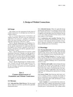
1 weld Connections Shear Plane Throat = w x Cos 450. = w w Root w FILLET weld . Electrodes should be selected to match the base metal. Use E70XX electrodes with steels that have a yield stress less than 60 ksi. Use E80XX electrodes with steels that have a yield stress of 60 ksi or 65 ksi. Nominal load capacity of weld , Rn = Fw Aw = [ w L ] Fw Design Strength, Rn = Fw Aw = [ w L ] Fw Where = Where Fw = nominal strength of the weld metal per unit area = FEXX. Fw based on the angle of the load to the longitudinal axis of the weld ( ): Fw = FEXX [ + Sin ]. Dr. Haque, ( weld Connections - Rev) Page 1 of 7.
2 Fillet weld symbols E70. 1/4 7 Near side (arrow side). 1/4 7. E70. Other side 1/4 7. E70. 1/4 7 Both sides E70. 1/4 7 weld all around Field weld E70. 1/4 7. Dr. Haque, ( weld Connections - Rev) Page 2 of 7. EXAMPLE 1: Determine the strength of the following welds. 8 . (a) 3/4 weld , 8 long, loaded along the weld 8 . 8 . 450. (c) 3/4 weld , 8 long, loaded at a 450 to (b) 3/4 weld , 8 long, loaded perpendicular to the weld the weld (a) Nominal Design Strength, Rn = Fw Aw = [ w L ] Fw Where = Rn = [ (3/4 )(8 )]( ) = kips (b) Fw = FEXX [ + Sin ] = FEXX ( ) { Sin = Sin (900 ) = 1}.
3 Rn = x = kips (c) Fw = FEXX [ + Sin ] = FEXX ( ) { = 450 }. Rn = x = kips Dr. Haque, ( weld Connections - Rev) Page 3 of 7. Example 2: Determine the design strength for C-shaped welds. Use E70XX. electrodes and a 3/16 Fillet weld . PL (A36 Steel). 8 . E70. 3/16 PL (A36 Steel). 10 . For 3/16 weld , 2-10 long, loaded along the weld Rw(L) = (3/16 )(2x10 )]( ) = kips For 3/16 weld , 8 long, loaded perpendicular to the weld Rw(T) = (3/16 )(8 )]( ) = Kips Without considering the weld and load orientation, weld Design Strength AISC Specification, Equation (J2-10a) (AISC Steel Manual 14th Ed.)
4 Rn = + = Kips weld Design Strength considering the added contribution of the transverse welds while reducing the contribution of the longitudinal welds, AISC Specification, Equation (J2-10b) (AISC Steel Manual 14th Ed.). Rn = ( ) + ( ) = Kips Select the largest one, Rn = ( )( ) = Kips Dr. Haque, ( weld Connections - Rev) Page 4 of 7. Example 3: Determine the LRFD design strength of the connection as shown in Figure. Follow the following steps: (a) Strength based on yielding in the gross section (b) Strength based on tensile fracture (c) Strength based on block shear failure (d) weld strength.
5 (e) What is the design strength of this connection ? PL (A36 Steel). 8 . E70. 5/16 PL (A36 Steel). 10 . SOLUTION: (a) Strength based on yielding in the gross section t Pn = t Fy Ag = (36 ksi) (8" x ") = Kips (b) Strength based on tensile fracture Ae = U x An t Pn = t Fu Ae AISC Specification TABLE , Case 1, U= 1. Ae = (1) (8" x ") = 4 Sq in. Dr. Haque, ( weld Connections - Rev) Page 5 of 7. t Pn = t Fu Ae = ( ) (58 ksi) (4 sqin) = 174 Kips. (c) Strength based on block shear failure Design Block Shear Strength = Rn where = Rn = Fu Anv + Ubs Fu Ant <= Fy Agv + Ubs Fu Ant Agv = (2 x 10")( ") = 10 sq in Anv = 10 sq in Ant = 8" x " = 4 sq in Ubs = for uniform tension stress Rn = (58 ksi)(10 sq in) + (1)(58 ksi)(4) = 580 kips Rn = (36 ksi)(10 sq in) + (1)(58 ksi)(4) = 448 Kips CONTROLS.
6 Rn = 448 = 336 kips (d) weld strength. For 5/16 weld , 2-10 long, loaded along the weld Rw(L) = (5/16 )(2x10 )]( ) = kips For 5/16 weld , 8 long, loaded perpendicular to the weld Rw(T) = (5/16 )(8 )]( ) = Kips AISC Specification (AISC Steel Manual 14th Ed.). Equation (J2-10a): Rn = + = Kips Equation (J2-10b): Rn = ( ) + ( ) = Kips Design Wed strength, Rn = ( )( ) = Kips (e) What is the design strength of this connection ? Based on (a), (b), (c), and (d), Yielding controls (a): The design Strength = Kips. Dr. Haque, ( weld Connections - Rev) Page 6 of 7. Backing bar Butt Groove weld Tee Groove weld Corner Groove weld Fig 1: Complete penetration groove welds Fig 2: partial penetration groove welds Dr.
7 Haque, ( weld Connections - Rev) Page 7 of 7.
