Transcription of Welding Procedure Specification (WPS) Sheet 1 of 3
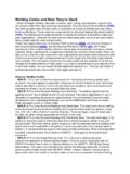
1 Welding Procedure Specification (WPS) ASME Boiler and Pressure Vessel Code , Section IX Sheet 1 of 3 Company Name: Address: 1 (877) WPS-WELD Welding Procedure Specification WPS No.: DEMO-WPS Revision No.: (0) Date: 12,12, 2005 Supporting PQR No. (s): DEMO-PQR Date: 11,12, 2005 BASE METALS (QW-403)P-No.: 4 Group No.: 1 Material Specification : SA-335 Type or Grade: P11 Welded to P-No.: 4 Group No.: 1 Material Specification : SA-234 Type or Grade: WP11, Class 1OR Chem. Analysis and Mech. Welded to Chem. Analysis and Mech. Qualified Thickness Range mm (in) Groove: 5 mm (3/16 in.)
2 To 60 mm ( in.)Fillet: UnlimitedQualified Diameter Range mm (in) Groove: All SizesFillet: UnlimitedOther information: This is a DEMO WPS from FIRST PROCESSSECOND PROCESS Welding Process (es):Gas Tungsten Arc Welding (GTAW)Shielded Metal Arc Welding (SMAW) Type (s):Manual Manual FILLER METALS (QW-404) AWS ClassificationElectrode-Flux Class (SAW)ER80S-G (see Sheet 3) E8016-B2 (see Sheet 3) SFA SpecificationSFA SFA Filler Metal 4 Weld Metal Analysis 3 Size of Filler Metals mm (in) mm (see Sheet 3) mm (see Sheet 3)Filler Metal Product Form Solid copper coated wireIron powder low hydrogen Max.
3 Weld Pass Thickness mm (in)1/8 Weld Metal Range: Groove mm (in)10 mm (3/8 in.)60 mm ( in.)Qualified Weld Metal Range: Fillet mm (in)UnlimitedUnlimitedWeld Deposit Chemistry__Flux Trade Name and Flux Type (SAW) N/AN/AConsumable Insert, Class and Size__Other information: This is a DEMO WPS from POSITIONS (QW-405) Position (s) of GrooveALL PositionALL PositionWelding ProgressionUpUpPosition (s) of FilletALL PositionALL Position PREHEAT (QW-406) Preheat Temp. C ( F)150 C150 CInterpass Temp. Max. C ( F)280 C280 CPreheat Maintenance C ( F)New JointNew Joint GAS (QW-408) Shielding Gas Type (Mixture)100% ArN/AFlow Rate lt/min.
4 (CFH) 7 to 9 Gas Type (Mixture) N/AN/AFlow Rate lt/min. (CFH)__Gas Backing (Mixture)N/AN/AFlow Rate lt/min. (CFH)__ POSTWELD HEAT TREATMENT (QW-407) Holding Temperature Range C ( F): 680 C + or - 10 CHolding Time Range: 1 hr/ in. (15 minutes Min.)Heating Rate C/hr ( F/hr): 120 C/hrMethod: FurnaceCooling Rate C/hr ( F/hr): 120 C/hrMethod: Open AirWPS No. DEMO-WPS Rev. (0) Sheet 2 of 3 ELECTRICAL CHARACTERISTICS (QW-409)Following data may also shown on Table below in this Sheet FIRST PROCESS SECOND PROCESSC urrent/ PolarityDCENDCEP Amps (Range)90 to120 100 to 130 Volts (Range)18 to 25 20 to 28 Wire Feed Speed (Range) mm/min (in/min)_ _ Travel Speed (Range) mm/min (in/min)Manual control Manual control Mode of Metal Transfer for GMAW (FCAW) N/AN/ATungsten Electrode Size mm (in) mm_Tungsten TypeSFA EWTh-2 TECHNIQUE (QW-410)
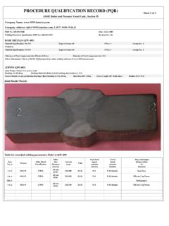
5 String or Weave Bead String Bead String and Weave Bead Multiple or Single Electrodes Single Single Multiple or Single Pass (per side) Multiple Multiple Orifice or Gas Cup Size5/8 in. Nozzle Size _ Contact Tube to Work Distance mm (in) _ _ Initial and Interpass Cleaning Brushing Brushing and Grinding Method of Back Gougingn/a n/a Oscillation_ _ PeeningNot Required Not Required Other information: Clean each layer before start Welding new passes/layers JOINTS (QW-402) Joint Design: Groove Design Used Backing Type: Metal Backing Material (Refer to both backing and retainers.)
6 : Same as base metalsJoint Details/ Sketch: Groove Details (or as per production drawing): Root Opening G: _ Root Face RF: _ Groove Angle: _ Radius (J-U): _Table for recorded Welding parameters; Refer to QW-409 Weld Layer(s)Pass No. (s)Process Filler Metal Classification Filler SizeDiameter mm (in) Current AmpsRange CurrentType & Polarity Wire Feed Speed Range mm/min(in/min) VoltsRange Travel Speed Range mm/min(in/min)Max. Heat InputkJ/mm (kJ/in)Or Remarks 1 1 GTAW ER80S-G mm 90-120 DCEN N/A 18-25 _ Root Pass 2 2 to 3 GTAW ER80S-G mm 90-120 DCEN N/A 18-25 _ 3 to n 4 to n SMAW E8016-B2 mm 100-130 DCEP N/A 20-28 _ Fill and Cap Passes Additional Notes: This is a DEMO-WPS prepared by online Welding software of Manufacturer or Contractor s Welding Engineer:Name: Jim Clark Signature: Title: Welding Engineer Date: 12, 12, 2005 Authorized by:Name: John Smith Signature: Title: QA Manager Date: 12,12, 2005 WPS No.
7 DEMO-WPS Rev. (0) Sheet 3 of 3 Heat Treatment (ASME Code s Guideline): PREHEAT TABLE:ASME Section I: Preheating from Appendix A (A-100) (a) 250 F (120 C) for material which has either a specified minimum tensile strength inexcess of 60,000 psi (410 MPa) or a thickness at the joint in excess of 1/2 in. (13 mm):(b) 50 F (10 C) for all other materials of P-No. 4 group. POSTWELD HEAT TREATMENT TABLE:ASME Section I: Mandatory Requirements for PWHT of Table PW-39 Min. Holding Temperature: 1,200 F (650 C) Min. Holding Time for Weld Thickness (Nominal):Up to 2 in. (50 mm): 1 hr/in. (2 min/mm), 15 min 2 in.
8 (50 mm) to 5 in. (125 mm): 1 hr/in. (2 min/mm)Over 5 in. (125 mm): 5 hr plus 15 min for each additional inch over 5 in. (125 mm)Heating rate: The weldment shall be heated slowly to the holding temperature, Min. 100 F (55 C)/hrCooling rate: Cool slowly in a still atmosphere to a temperature not exceeding 800 F (425 C) For Non-Mandatory conditions of PWHT, See Notes (1), (2) of Table PW-39 WPS Qualified Range (ASME IX Guideline): Qualified Positions (Groove, Fillet): All Positions for Plate or Pipe. Unless specifically required otherwise by the Welding variables (QW-250), aqualification in any position qualifies the Procedure for all positions.
9 The Welding process and electrodes must be suitable for all positionspermitted by the WPS (ASME Section IX, QW-203). (For impact test application, there are some restrictions for Welding in vertical-uphillprogression position; See ASME Section IX, ) Qualified Thicknesses (Groove, Fillet): 3/16 in. (5 mm) Min., 2T Max. (Plate or Pipe)[For GMAW-Short Circuit Arc, when T is less than 1/2 in. (13 mm): Max. ASME IX, ][For impact test application, except ESW process: Min. Qualified Thickness is either T or 5/8 in. (16 mm), whichever is less; This variable doesnot apply when a WPS is qualified with a PWHT above the upper transformation temperature or when an austenitic material is solution annealedafter Welding .]
10 ASME IX, ][For ferrous base metals other than P-No. 7, 8 and 45 (when test coupon receives a PWHT above the upper transformation temperature): ASME IX, ][For any weld pass greater than 1/2 in. (13 mm) thick: Max. (Except GTAW process). ASME IX, ]T: Thickness of Test Plate or Pipe Wall in PQR (ASME Section IX, Table ) Qualified Diameters (Groove, Fillet): All Nominal Pipe (Tube) Sizes, within Qualified Thicknesses in PQR WPS Base Metal P-Numbers Allowed by PQR: Any metals of the same P-No. 4, plus combination between any metal from P-No. 4 to any metalfrom P-No. 3 or P-No. 1 (ASME Section IX, QW-424) Qualified WPS Filler Metal Allowed by PQR: Only Filler Metal categories with the same F-number and same A-number tested in PQR.