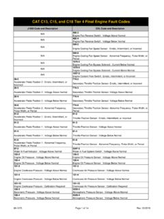
Transcription of Welding Repair for Structural Cracks - Allied Systems
1 1 Section 8-1 Allied Systems Co. reserves the right to make changes to new equipment without incurring the obligation to make such changes to equipment previously , REV. 8-2012 Welding Repair for Structural CracksGeneralYour regular maintenance schedule should include an inspection of the chassis and other major weldments at regular intervals. Allied Systems Company sug-gests that you clean and inspect your unit for Cracks quarterly, more often in severe applications. Once a crack is found it s important to Repair it immediately us-ing the procedures outlined in this the years we have observed many successful and unsuccessful attempts to Repair Cracks . This ser-vice procedure was developed to outline proper crack Repair procedures procedures that have proven to be successful.
2 All crack repairs should be carried out by a certifi ed Fundamentals(Preheat, Interpass Temperatures, and Postheat)Preheating involves heating the base metal immedi-ately surrounding the weld to a specifi c temperature prior to Welding . There are four reasons to preheat:1. It slows cooling, producing more ductile metallur-gical structure with greater resistance to cracking;2. Slower cooling provides an opportunity for hydro-gen that may be present to diffuse out harmlessly, reducing potential for cracking;3. It reduces stresses in the weld and adjacent base metal, which is especially important in highly restrained joints; and4. It raises some steels above the temperature at which brittle fracture would occur in fabrication.
3 Preheat may be applied in a furnace, using electri-cal strip heaters, induction, radiant heaters, or heating torches. When heating the joint to be welded, the preheat tem-perature should be established at a distance at least equal to the thickness of the thickest member, but not less than 3 inches (75mm) in all directions from the Welding point. To ensure that the full material volume surrounding the joint is heated, it is recommended practice to heat the opposite side of that which is to be welded and to measure the surface temperature adjacent to the temperature refers to the temperature of the material in the weld area immediately before the second and each subsequent pass of a multi-pass weld. In practice, the minimum specifi ed interpass temperature is often equal to the minimum specifi ed preheat temperature.
4 Interpass temperature is prob-ably more important than preheat temperature with regard to the mechanical and microstructural proper-ties of weldments. For instance, the yield and ultimate tensile strengths of the weld metal are both a function of interpass temperature. High interpass temperature tends to reduce weld metal minimum interpass temperature must be suffi cient to prevent cracking, while the maximum interpass temperature must be controlled to provide adequate mechanical properties. The following variables must be considered: time between passes, base metal thickness, preheat temperature, ambient conditions, heat transfer characteristics, and heat input from application of postweld heat is often used to improve the properties of the weldment.
5 The goal of applying postweld heat is to increase the resistance to brittle fracture and relaxing residual stresses. Other desired results from post heat may include hardness reduction and material strength Preheat and Interpass TemperaturesOne accepted method of controlling the preheat and interpass temperature is to use two temperature indi-cating crayons available at your local Welding supply store. A surface applied temperature indicating crayon (often referred to by the trade name, Tempilstik) melts when the material to which it is applied reaches the crayon s melting temperature. The crayons are avail-able in a variety of melting temperatures, and each individual crayon is labeled with its approximate melt-ing temperature indicating crayon is typically used to measure both minimum specifi ed preheat temperature and the minimum specifi ed interpass temperature, while the second is a higher temperature crayon used to measure the maximum specifi ed interpass welder fi rst heats the joint to be welded and checks the base metal temperature at the designated location (typically 3 inches from the weld), by marking the base metal with the fi rst temperature indicating crayon.
6 When the minimum specifi ed preheat tem-perature is reached (when the fi rst crayon melts), the fi rst Welding pass can begin. Immediately before the second and subsequent passes, the minimum and maximum interpass temperature should be checked in the proper location (typically 1 inch from the weld). The lower temperature crayon should melt, indicating that the temperature of the base metal is greater than the melting temperature of the crayon, while the higher temperature crayon should not melt, indicating that the base metal temperature is not above the maximum interpass the lower temperature crayon does not melt, addi-tional heat should be applied to the joint until the cray-on mark on the base metal melts. And, if the upper temperature crayon melts, the joint should be allowed to slowly cool until the upper temperature crayon no longer melts, while the lower temperature crayon does melt.
7 Then the next Welding pass can begin. A joint shall be completely welded before it is allowed to cool below the specifi ed temperature to prevent a general rule, the interpass temperature must be maintained for a distance at least equal to the thick-ness of the thickest welded part (but not less than 3 inches, or 75mm) in all directions from the point of Welding . To ensure that the interpass temperature does not exceed the maximum in the base metal im-mediately adjacent to the weld, the maximum inter-pass temperature should be measured at a distance of 1 inch from the : On your Wagner unit, postweld heat is ap-plied to swivel boxes on Chipdozers, and on Lum-berjacks it is applied to swivel boxes, tail posts and wheel hubs. Allied Systems Company recom-mends that these complex weldments be returned to the factory when Repair Welding is and Maximum Preheat and Interpass TemperaturesYour Wagner unit is constructed using medium-strength and high-strength steels.
8 Typically, the boom and certain parts of the carriage, axle housing and swivel box on a Lumberjack are constructed of high-strength steel. The swivel box and bucket on a Chipdozer are constructed of high-strength steel. Other parts of your unit are mostly constructed using medium-strength steel. The preheat temperatures and interpass temperatures listed below are intended to be used at all times (for all steels) when Welding on your Wagner of Thickest Part at Point of WeldManual or Semi-Automatic Gas Metal-Arc Welding , Flux Cored Arc Welding or Manual Shielded Metal-Arc Welding with Low Hydrogen ElectrodesMinimum Preheat TemperatureMaximum Interpass TemperatureTo & Including 100 F (38 C)400 F (205 C) to 1 175 F (80 C)400 F (205 C)1 to 2 225 F (110 C)450 F (230 C)Over 2 275 F (135 C)450 F (230 C)Table 1.
9 Minimum Preheat and Maximum Interpass Temperatures3 When joining steels of different thicknesses with groove welds, the preheat and interpass temperatures for the average plate thickness shall be used. For fi llet welds, the preheat shall be used for the thickest plate being moisture is present on the base metal it shall be preheated to 220 F (105 C) before Welding for repairing Structural Cracks Use the following instructions to Repair Structural Cracks : 1. Read, understand, and heed all safety information found in your operator s Before starting work move the machine to a level surface, engage the parking brake, and stop the Chock the Set the Battery Disconnect switch to OFF before performing any Welding . Turn the switch coun-terclockwise to disconnect the batteries.
10 If your machine is not equipped with a battery disconnect switch, disconnect battery Disconnect ECM (Electronic Control Module). The ECM connector is located on the Disconnect PLC (Programmable Logic Control-lers) or electronic control modules if so Steam clean the entire machine. Inspect the unit for Remove crack and/or defective material with air carbon arc process or equivalent while creating a weld joint consistent with AWS B-P2 for fl at posi-tion Welding or AWS B-P4 when Welding in the vertical position. See Figures 1 & 2 Grind clean the surface(s) to be Verify removal of crack with a magnetic particle test or Preheat to the temperature specifi ed in Table 1. Preheat varies depending on material Use Dual Shield 11 71 All-position electrodes and AWS Class E71T-1 or Inspect fi nished weld for smoothness and Repaint the Repair area to protect against questions or concerns, please contact your local dealer or Allied Systems Company Service Depart-ment at (503) 625-2560.